DELL ALIENWARE® M17x MOBILE User Manual

Before Setting Up Your Laptop
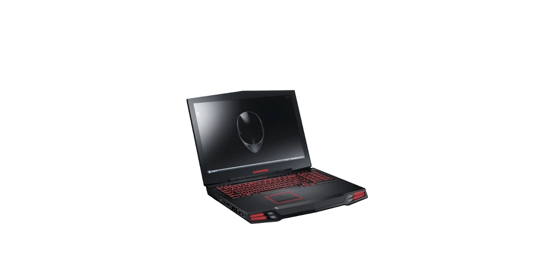
Congratulations on the purchase of your Alienware M17x!
Read all safety and setup instructions before connecting your new laptop. Begin by carefully opening the box and removing all components that were shipped to you.
Before setting up your laptop or components, see the included invoice to verify that all items ordered are present and be sure to inspect all items for any physical damage that may have occurred during shipment. Report any missing components or damaged items to customer service within 5 days of receiving the shipment. Anything reported missing or damaged after the first 5 days of receiving a shipment will not be honored. Some of the most common items to check for include:
- Laptop and AC adapter with power cable
- Microsoft CD‑key located at the bottom of the laptop
- Monitor with power cable and video cable (if ordered)
- Keyboard(if ordered)
- Mouse(if ordered)
- Multimedia speakers and sub‑woofer (if ordered)
- Joystickcontrollers (if ordered)
You may also need a small flathead and/or a Phillips head screwdriver for connecting peripheral cables to the laptop.
Product Documentation and Media
The documentation that ships with your Alienware laptop is designed to provide answers to many of the questions that may arise as you explore your new laptop’s capabilities. You may see the documentation for technical information or general use as needed to answer questions in the future, or aid you in finding answers and solutions. The media included with your laptop is referenced in some sections of the documentation and may be needed to complete certain tasks. As always, our technical support staff is available to assist you.
Placing Your Laptop
WARNING: Do not place the laptop near or over a radiator or heating vent. If your laptop is placed in a cabinet, ensure that adequate ventilation is provided. Do not place thelaptop in a humid location or in any area where the laptop may be exposed to rain or water. Be careful not to spill liquid of any kind on or into the laptop.
When placing your laptop, ensure that:
- It is placed on a surface that is both level and
- The power and other cable connectors are not jammed between the laptop and a wall or any other object.
- Nothing obstructs airflow in front of, behind, or below the
- The laptop has enough room so that optical drives and other external storage drives can be easily accessed.
System Setup Options
NOTE: Depending on your computer and installed devices, the items listed in this section may not appear, or may not appear exactly as listed.
NOTE: For the updated system setup information, see the Service Manual atsupport.dell.com/manuals.
| Main Menu | |
| System Time (hh:mm:ss) | Displays the system time. |
| System Date (mm/dd/yyyy) | Displays the system date. |
| Alienware | Displays the model number of your computer. |
| Service Tag | Displays the service tag of your computer. |
| BIOS Version | Displays the BIOS version. |
| EC Version | Displays the EC firmware version. |
| ME Version | Displays the Intel ME firmware version. |
| Sandy Bridge Version | Displays the Sandy Bridge version. |
| Main Menu | |
| CPU | Displays the type of processor installed. |
| CPU Frequency | Displays the speed of the processor. |
| CPU L3 Cache | Displays the processor cache size. |
| CPUID | Displays the ID of the processor. |
| Integrated Graphics | Displays the integrated graphics. |
| Discrete Graphics 1 | Displays the primary discrete graphics. |
| Discrete Graphics 2 | Displays the secondary discrete graphics. |
| Total Memory | Displays the total memory available in your computer. |
| Memory Bank 0 | Displays the memory size installed in DIMM 0. |
| Memory Bank 1 | Displays the memory size installed in DIMM 1. |
| SATA Hard Drive | Displays the installed SATA hard drive model. |
| Advanced Menu | |
| Intel SpeedStep | Allows you to enable or disable the Intel SpeedStep technology. Disabling this feature may improve performance, but will greatly reduce battery life. |
| Virtualization | Allows you to enable or disable the Intel Virtualization technology. |
| USB Emulation | Allows you to enable or disable the USB emulation feature. This feature defines how the BIOS, in the absence of a USB-aware operating system, handles USB devices. USB emulation is always enabled during POST. NOTE: You cannot boot any type of USB device (floppy, hard drive, or memory key) when this option is off. |
| USB Wake Support | Allows you to enable USB devices to wake the computer from standby or to disable the USB wake support feature. NOTE: If USB Powershare is enabled, a device connected to the USB Powershare connector may not wake the computer. |
| Advanced Menu | |
| USB Power Share | Allows you to charge USB devices when the computer is turned off or in standby mode. · AC Only: Charge USB devices when connected to AC adapter only. · AC and Battery: Charge USB devices when connected to AC adapter and when the computer is running on battery. · Disabled: Disables USB PowerShare. |
| Integrated Network | Allows you to enable or disable the on‑board LAN controller. · Disabled: Internal LAN is disabled and is not visible to the operating system. · Enabled: Internal LAN is enabled. |
| High Definition Audio | Allows you to enable or disable the internal high definition audio device. · Disabled: The internal audio device is disabled and is not visible to the operating system. · Enabled: The internal audio device is enabled. |
| SD Card Reader | Allows you to enable or disable the internal SD card reader. |
| Advanced Menu | |
| CPU Turbo Mode | Allows you to enable or disable the Intel CPU turbo mode performance option. |
| Performance Menu | Allows you to configure fields in the Performance Options sub-menu (for more information, see “Performance Options Sub‑Menu“ on page 60). |
| Extended ICC | Allows you to configure fields in the Extended ICC sub-menu (for more information, see “Extended ICC Sub‑Menu“ on page 62). |
| SATA Operation | Allows you to configure the operating mode of the integrated SATA hard drive controller. · AHCI: SATA is configured for AHCI mode. · RAID: STAT is configured for RAID mode. |
| SATA HARD DRIVE 1 | Displays the installed primary SATA hard drive model. |
| SATA HARD DRIVE 2 | Displays the installed secondary SATA hard drive model. |
| Advanced Menu | |
| Adapter Warnings | Allows you to choose if the computer should display warning messages when you use AC adapters that are not supported by your computer. · Disabled: BIOS will not detect unsupported AC adapters and will not display any message to screen. · Enabled : BIOS will detect unsupported AC adapters and display an error to screen. |
| Charger Behavior | Allows you to enable or disable battery charging. |
| Primary Display
Performance Options Su | Allows you to choose a primary display.
b-Menu |
| Performance Options Sub-Menu | |
| Override Turbo settings | Allows you to override CPU turbo mode settings. |
| Long Duration Power Limit | Allows you to set the turbo mode power limit 1 value in watts. |
| Long Duration Time Window | Allows you to set the turbo mode time 1 value in seconds. |
| Set Short Duration Power Limit | Allows you to enable or disable short duration power limit. |
| Short Duration Power Limit Options | Allows you to set the turbo mode power limit 2 value in watts. |
| Memory Overclocking | |
| Memory Override Support | Allows you to enable or disable the memory override option support. · Disabled: The memory override support is disabled. · Enabled: Displays additional memory override support options. |
| Memory Voltage | Allows you to increase memory voltage. |
| Performance Options Sub-Menu | |
| Memory Frequency | Allows you to set memory frequency. |
| XMP DIMM Profile
Extended ICC Sub-Menu | Allows you to configure different XMP options. |
Before You Begin
This section provides procedures for removing and installing the components in your laptop.
Unless otherwise noted, each procedure assumes that the following conditions exist:
- You have performed the steps in “Turning Off Your Computer” and “Before Working Inside Your Computer” in this
- You have read the safety information that shipped with your
- Component can be replaced or—if purchased separately—installed by performing the removal procedure in reverse
The procedures in this section may require the following tools:
- Small flat-blade screw driver
- Phillips screw driver
Before Working Inside Your Computer
Use the following safety guidelines to help protect your computer from potential damage and to help to ensure your own personal safety.
WARNING: Before working inside your laptop, read the safety information that shipped with your computer. For additional safety best practices information, see the
Regulatory Compliance Homepage at www.dell.com/regulatory_compliance.
CAUTION: Handle components and cards with care. Do not touch the components or contacts on a card. Hold a card by its edges. Hold a component such as a processor by its edges, not by its pins.
CAUTION: Only a certified service technician should perform repairs on your computer. Damage due to servicing that is not authorized by Dell is not covered by your warranty.
CAUTION: To avoid electrostatic discharge, ground yourself by using a wrist grounding strap or by periodically touching an unpainted metal surface (such as a connector on the back of the computer).
CAUTION: When you disconnect a cable, pull on its connector or on its pull-tab, not on the cable itself. Some cables have connectors with locking tabs; if you are disconnecting this type of cable, press in on the locking tabs before you disconnect the cable. As you pull connectors apart, keep them evenly aligned to avoid bending any connector pins. Also, before you connect a cable, ensure that both connectors are correctly oriented and aligned.
Replacing the Battery Pack
This battery pack can easily be removed and replaced. Ensure that the laptop is properly shut
down before changing the battery pack.
CAUTION: To avoid damage to the laptop, use only the battery designed for this particular Alienware laptop. Do not use batteries designed for other Alienware or Dell laptops.
To remove the battery pack:
- Followthe instructions in “Before You Begin” on page 68.
- Shutdown the
- Turn the laptop
- Slide the battery latch to the unlock position as The battery pack pops up.
- Remove the battery
Upgrading or Replacing Memory
Your laptop is equipped with a configurable memory unit. The industry standard JEDEC PC3-10600 (DDR3) SODIMM memory module connectors are available for memory upgrade.
NOTE: If you purchased a dual‑core processor, your computer supports only memory module connectors DIMM 1 and DIMM 2.
NOTE: The table below illustrates one possible way the system memory can be configured. You can also configure the system memory by installing memory modules in connectors DIMM 3 and DIMM 4.
| Memory connector DIMM 1 | Memory connector DIMM 2 | Memory connector DIMM 3 | Memory connector DIMM 4 | Total memory |
| 2 GB | 2 GB | — | — | 4 GB |
| 2 GB | 4 GB | — | — | 6 GB |
| 4 GB | 4 GB | — | — | 8 GB |
| 8 GB | 8 GB | — | — | 16 GB |
| 8 GB | 8 GB | 8 GB | 8 GB | 32 GB |
TROUBLESHOOTING
Basic Hints and Tips
- Computer does not power on: Is your AC adapter cable securely connected to a working electrical outlet? If connected to a power strip, ensure that the strip is actually
- Connections: Check all the cables to ensure that there are no loose connections
- Power Savings: Ensure that your computer is not in hibernate or standby mode bypressing the power button for less than 4 The power status light will fade from blue to black while in standby mode; in hibernate mode it will be off.
- Brightness: Check and adjust the brightness of the display by pressing the key
combinations <Fn><F4> or <Fn><F5>.
- Display Choice: Press the key combination <Fn><F6> to ensure that the computer is not set to “External Only” display.
- Useonly the AC adapter that shipped with your
Backup and General Maintenance
- Alwaysbackup your important data on a regular basis and keep copies of your operating system and software safe. Do not forget to note the serial numbers if you are storing them outside of their original cases ‑ for example, in a CD
- Run maintenance programs as often as you can. You may schedule these programs torun at times when you are not using your computer. You can use those provided with your operating system, or buy more powerful, dedicated programs to do
- Writedown your passwords and keep them safe (away from your computer). This is especially important if you choose to password‑protect your computer’s BIOS and operating
- Documentvital settings such as network, dialup, mail and Internet setting.
Answers to Common Problems
System
The computer fails the POST
The Power On Self Test (POST) ensures that the computer meets all the necessary system requirements and that all hardware is working properly before starting the remainder of the boot process. If the computer passes the POST, the computer will continue to start normally. However, if the computer fails the POST, the computer will generate a single beep to indicate a general failure and an error message will be displayed. For assistance, contact Alienware Technical Support (see “CONTACTING ALIENWARE“.
BASIC Specifications
| Computer Model |
| Alienware M17x-R3 |
| Dimensions | |
| Height | |
| Front | 44.5 mm (1.75 inches) |
| Back | 45.0 mm (1.77 inches) |
| Width | 410.0 mm (16.14 inches) |
| Depth | 304.0 mm (11.97 inches) |
| Weight with 9-cell battery and optical drive (starting at) | 4.26 kg (9.40 lb) NOTE: The weight of your laptop will vary depending on the configuration ordered and the manufacturing variability. |
| Processor and System Chipset | |
| Processor | · Intel Core i5 · Intel Core i7 |
| L2 cache | 256 KB |
| L3 cache | up to 8 MB |
| Bus clock | 100 MHz |
| System chipset | Mobile Intel HM67 Express Chipset |
| SDRAM bus width | one or two 64-bit channels of DDR3 memory up to 1333 MHz |
| Processor address bus width | 32 bits |
| Processor data width | 64 bits |
| BIOS SPI Flash Memory | 32 Mbit |
| Graphics bus | PCIe x16 bus |
| Memory | |
| Connectors | four internally-accessible DDR3 using JEDEC SODIMM sockets |
| Capacities | 2 GB, 4 GB, and 8 GB |
| Memory type | up to 1333 MHz unbuffered non-ECC dual-channel DDR3 configuration |
| Memory configurations possible | 4 GB, 6 GB, 8 GB, 16 GB, and 32 GB |
| Ports and Connectors | |
| Network adapter | one RJ45 connector |
| USB | two 4-pin USB 2.0 and 3.0 compliant connectors |
| eSATA/USB combo | one 7-pin/4-pin eSATA/USB 2.0-compliant combo connector with PowerShare |
| HDMI input and output | one 19-pin connector |
| Mini-DisplayPort | one 20‑pin connector |
| VGA | one 15‑hole connector |
| Audio | two stereo headphones/speakers connectors one microphone‑in connector |
| S/PDIF | one headphone/S/PDIF combo connector |
| Media Card Reader | one 9-in-1 slot |
| Communications | |
| Network adapter | 10/100/1000 Mbps Ethernet LAN on system board |
| Wireless
Video | · one half Mini‑Card slot · one full Mini‑Card slot · Bluetooth; Wireless Display (optional); WirelessHD (optional) |
| Video | |
| Video memory | |
| Integrated | 512 MB dedicated video memory (for total system memory greater than 4 GB) |
| Discrete | · 1.5 GB · 1.0 GB · 2.0 GB |
| External display support
Audio | HDMI, Mini DisplayPort, VGA, WiDi (optional), and WirelessHD (optional) |