
Cobra 1500W Power Inverter Owner Manual
INTRODUCTION
Thank you for purchasing the Cobra PRO Series Power Inverter. Used properly, this Cobra product will give you reliable power to run your appliances and devices. Please read this manual thoroughly before you install and set up your new power inverter.
HOW YOUR POWER INVERTER WORKS
The Cobra PRO Power Inverter is a power conversion device that is designed and built to operate from low Voltage DC (Direct Current) power from your vehicle battery and converts it to standard 115 Volt AC (Alternating Current) power like you have in your home. This conversion process allows you to use many of your household appliances and electronic products in automobiles, RVs, boats, trucks and virtually anywhere else with a 12 Volt battery.
PRODUCT SERVICE AND SUPPORT
For any questions about operating or installing this new Cobra product, PLEASE CONTACT COBRA FIRST…do not return this product to the retail store. The contact information for Cobra will vary depending on the country in which you purchased and utilize the product. For the latest contact information, please go to www.cobra.com/support or call 1-800-543-1608.If your product should require factory service, please go to www.cobra.com/support and follow the instructions.
WHAT’S IN THE BOX
- PRO Power Inverter (1500W, 2500W or 3000W)
- (2) 48-inch #4AWG Power Cables (PRO 1500W)
- (4) 48-inch #4AWG Power Cables (PRO 2500W)
- (4) 48-inch #2AWG Power Cables (PRO 3000W)
- Terminal Protector Boots
- Quick Start Guide
- Remote On/Off Controller with Fast Charge USB (PRO 3000W only)
OPTIONAL ACCESSORIES
- CPIALCDG1 – Remote On/Off controller with Fast Charge USB

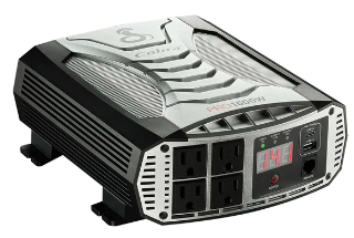
CONTROLS AND CONNECTIONS
Cobra PRO 1500W Features

- A. Negative Power Input Terminal
- B. Cooling Fans – regulate the temperature of the inverter, turning on when temperature exceeds the preset limit, and turning off when the temperature reduces
- C. Positive Power Input Terminal
- D. Green LED – Battery Voltage Indicator (V)
- E. Yellow LED – Output Power Indicator. When active, output power in is kilowatts (kW)
- F. Red LED – Output Power Indicator. When active, output power is in Watts (W)
- G. (4) GFCI Protected AC Outlets
- H. Digital Display showing Battery Voltage (V), Power in kilowatts (kW),Power in Watts (W) and Error Codes
- I. USB-C Fast Charge port (5V/9V/15W)*
- J. USB-A Fast Charge port (5V/9V/15W)*
- K. Port for Cobra Remote On/Off Controller with Fast Charge USB (Sold Separately)*
- L Power Button
- M. Power Cables
- N. Inverter Terminal Protector Boots
- O. Cobra Remote On/Off Controller with Fast Charge USB (Sold Separately).

- A. Negative Power Input Terminal
- B. Cooling Fans – regulate the temperature of the inverter, turning on when temperature exceeds the preset limit, and turning off when the temperature reduces
- C. Positive Power Input Terminal
- D. Green LED – Battery Voltage Indicator (V)
- E. Yellow LED – Output Power Indicator. When active, output power in is kilowatts (kW)
- F. Red LED – Output Power Indicator. When active, output power is in Watts (W)
- G. (4) GFCI Protected AC Outlets
- H. Digital Display showing Battery Voltage (V), Power in kilowatts (kW), Power in Watts (W) and Error Codes
- I. USB-C Fast Charge port (5V/9V/15W)**
- J. USB-A Fast Charge port (5V/9V/15W)**
- K. Port for Cobra Remote On/Off Controller with Fast Charge USB (Sold Separately)*
- L Power Button
- M. Power Cables
- N. Inverter Terminal Protector Boots
- O. Cobra Remote On/Off Controller with Fast Charge USB (Sold Separately)*
IMPORTANT PRODUCT /SAFETY INFORMATION
Before installing and using your Cobra power inverter, please read these general precautions and
warnings.Special attention must be paid to the CAUTION and WARNING statements in the manual.
CAUTION: Statements specify conditions which could cause damage to the unit or other equipment.
WARNING: Statements identify conditions that could result in personal injury or loss of life.General Precautions
- Never install the inverter in a boat’s engine compartment where gas and battery fumes are present.
- Do not operate the inverter if it has been dropped or damaged in any way.
- Do not open the inverter; it contains no user-serviceable parts. Attempting to service unit could
cause electrical shock.
NOTE: Internal components remain charged after all power is disconnected.
- Do not expose the inverter to rain, snow, bilge water or spray.
- . Do not obstruct the ventilation openings.
- Do not install the inverter in zero-clearance compartment.
- Do not allow water or liquids in contact with the power inverter
- Do not use appliances with damaged or wet cords.
CAUTION: This inverter should be used in negative ground applications only.
POWER CONSUMPTION
For each piece of equipment you will be operating from the power inverter, you must determine the battery’s reserve capacity (how long the battery can deliver a specific amount of current – in automotive batteries, usually 25 ampere) or ampere-hour capacity (a measure of how many amperes a battery can deliver for a specified length of time).Example – Ampere-hour capacity: a battery with an ampere-hour capacity of 100 ampere-hours can deliver 5 ampere for 20 hours before it is completely discharged.To determine the battery ampere-hour capacity you require:
- Determine how many Watts each piece of equipment consumes. This can normally be found on the product label. If only the Amperage is provided, then multiply the Amps by 115 to determine the power in Watts.
- Estimate how long you need your appliance to run.
- Now calculate the Amp-hour rating for the battery. You can do this by multiplying the total AC load (in Watts) by the length of time (in Hours) needed to run your appliance. This will give you the Watt-Hours needed.

INSTALLATION REQUIREMENTS
The inverter must be installed in an area that meets all of the following requirements:
- Dry – Do not place in an area where water can drip or splash on the inverter.
- Cool – Ambient air temperature should be between 30°F and 105°F (0°C and 40°C).The cooler the better.
- Ventilate – Allow at least one inch (three cm) of clearance around the inverter for proper airflow.Make sure that ventilation openings on the ends of the unit are not obstructed.
- Safe – Do not install the inverter in the same compartment as a battery or in any compartment that contains flammable liquids such as gasoline.
- Close to Battery – Install unit as close to battery as possible (without being in the same compartment) to minimize the length of cable required to connect the inverter to the battery. It is better and cheaper to run longer AC wires than longer DC wires (cables).
CONNECTING TO A VEHICLE BATTERY
Power wire and wiring are very important to the performance of the inverter. Because the inverter has a
low voltage, high current input, low resistance wiring is essential between the battery and inverter. This is
so it can deliver the maximum amount of energy to the load.For safety reasons, it is recommended to install a properly rated ANL fuse (not included) on the red cable as close to the positive (red) battery terminal as possible. If you have a dual cable installation, install a properly rated ANL
Fuse on each red cable. Cut about 12 inches from ring terminal and install fuse. Use (1) 150 Amp ANL fuse or equivalent for the PRO 1500W, (2) 150 Amp ANL fuses or equivalent for the PRO 2500W, or (2) ANL 200 Amp ANL fuses or equivalent for the PRO 3000W power inverter.Do not use aluminum wire. Aluminum has about one-third more resistance than copper wire of the same size, plus it is difficult to make good, low-resistance connections to aluminum wire. Your PRO Power Inverter comes with heavy duty copper cladded cable for connections between the battery and inverter.Keep the cable length as short as possible. The recommendation is no more than six feet. This will keep the voltage drop to a minimum.
COBRA PRO 1500W INSTALLATION

CHANGING THE LOW VOLTAGE ALARM SETTING
To Change the Low Voltage Alarm Seeing:
- Connect the Remote On/Off Controller with Fast Charge USB (Optional on the 1500W and 2500W inverter models).
- Press and hold the POWER button for 5 seconds or until Input Voltage LED turns blue.
 Once blue, the Battery Low Voltage Alarm will be set to sound when your battery Voltage reaches
10.5 Volts. The power inverter will automatically shut down when battery voltage reaches 9.5 Volts to protect the battery from deep discharge (so you can start your vehicle). The setting will not change when the inverter is turned off or the battery is disconnected. To set the inverter back to the Battery Low Voltage Alarm Default Setting at 11.5 Volts, follow steps 1 and 2.
 Once blue, the Battery Low Voltage Alarm will be set to sound when your battery Voltage reaches
OPERATING INDICATORS
Power on – The Voltage Input and Power Output indicators automatically toggle between input and output values at three-second intervals. The three LEDs indicate the mode the meter is in and the three digits indicate the voltage or power value.
Current Overload Protection – If the inverter is overloaded, it will shut down to protect itself. The meter will flash as shown to indicate Overload Protect.To restore normal operation, disconnect the excessive load and turn the unit Off and On again using the Power Button.
Short Circuit Protection – If the AC output of the inverter is short-circuited for one second or more, it will shut down to protect itself. The meter will flash as shown to indicate Short Circuit Protect and an alarm will sound. To restore normal operation, disconnect the short circuit and turn the unit Off and On again using the Power Button.
Low Voltage Protection – If the DC input voltage drops below the alarm threshold of 11.3V the meter will flash as shown to indicate Low Voltage Protection, but the unit will continue to operate. If the input voltage drops to 10.0V or less, the inverter will shut down to protect itself, the meter will continue to flash as shown, and an alarm will sound. To restore normal operation, return the DC input voltage to at least 12V. The inverter will automatically return to normal operation.
TROUBLESHOOTING GUIDE
| Problem/Symptom | Possible Causes | on |
| Low output voltage | Overload | Reduce the load. |
| No output voltage | Low input voltage | Recharge battery. Check connections and cable. |
| No output voltage after prolonged use | Thermal shutdown | Allow inverter to cool off. Reduce load, continuous operation input current required. Improve ventilation; make sure ventilation openings in the inverter are not obstructed. Reduce ambient temperature. |
| No output voltage, “Protect” indicator lighted | High input voltage | Make sure the inverter is connected to 12V battery. Check regulation or charging system. |
| No output voltage | Short circuit | Check load for proper operation. |
| No output voltage | Inverter switched off
No power to inverter Reverse DC polarity | Turn inverter on. Check wiring to inverter. Observe correct polarity. |
| Low battery alarm on all the time | Poor DC wiring Poor battery condition | Check connections. Make sure battery is fully charged. |
SPECIFICATIONS
| Specifications: | COBRA REMOTE ON/OFF CONTROLLER |
| Model | CPIALCDG1 |
| USB-A Output Port | 5V/2A/10W |
| USB-C Output Port | 5V/2A/10W |
| Operating Temperature | -10°C/14°F – 40°C/104°F |
| Storage Temperature | -40°C/-40°F – 65°C/149°F |
| Power Cable Length: | 15-feet #16 AWG |
| Dimensions | 3.35″ x 3.35″ x 1.64″ |
| Net Weight | .11 lbs |
REFERENCE
https://www.grupocobra.com/en/


