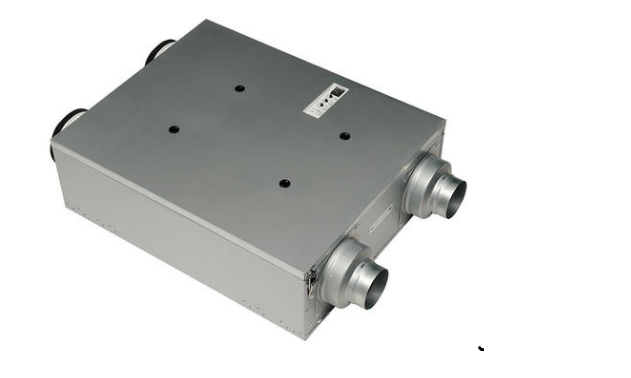
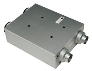
Panasonic FV-SW20VEC1 Intelli Balance
GENERAL SAFETY INFORMATION
For Your Safety
To reduce the risk of injury, loss of life, electric shock, fire, malfunction, and damage to equipment or property, always observe the following safety precautions. Explanation of symbol word panels The following symbol word panels are used to classify and describe the level of hazard, injury, and property damage caused when the denotation is disregarded and improper use is performed.
WARNING I De�ote? � potential hazard that could result in death or serious inJury. I A (A LJ TI Q N I Denotes a hazard that could result in minor injury . l Denotes a hazard that could result in property damage. The following symbols are used to classify and describe the type of instructions to be observed
Th is symbol is used to alert users to a specific operating procedure that must not be:)I performed.
A Th is symbol is used to alert users to a specific operating procedure that must be V followed in order to operate the unit safely. Th is symbol is used to alert users not to disassemble the equipment.
WARNING
- Do not install using methods not approved in the instructions. A V Installation must be performed by qualified person(s) in accordance with all applicable
- codes and standards, including fire-rated construction. Otherwise, a fire may be caused.
- Disconnect power source before working on the product.
(1) Do not disassemble the unit. It may cause fire or electric shock. - Never install the unit in a high humidity space.
- Do not spray flammable cleaner directly onto the controller.
- “‘- Do not touch the controller with wet hands or pour water on the controller,
- I it may cause fire or electric shock.
- Do not install in a place where flammable gas may leak.
- Discontinue use immediately if abnormal operation occurs.
- Do not use the unit for any purpose other than is what is intended
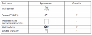
SUPPLIED ACCESSORIES
DIMENSIONS
INSTALLATION
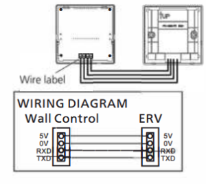
1. wiring preparation
INSTALLATION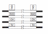
2. installing the wall control
- Open the knock-out hole and remove maintenance plate 1 and 2 and wiring
- Thread cables through conduits respectively and install the conduits into knock-out holes
- Insert cables into the corresponding terminals of product. Make sure the lead wire labels correspond to the terminal label and the screw of terminal securely fastens the copper wire and no copper wire is expo-sed

- Re-install the wiring covers and maintenance plates.
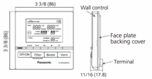
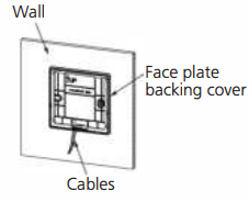
- Remove the face plate backing cover from the backing plate with a small flat screwdriver
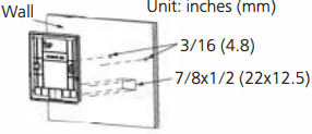
- Temporarily put the face plate backing cover on the wall, mark terminal hole and screw positions

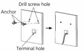
- Remove the face plate backing cover, cut the terminal hole and drill screw holes (<D5/32 ft (<D4 mm)).
- Insert wall anchors, and fix the face plate backing cover on the wall with two screws

- Route the cables form the unit to the terminal hole

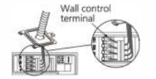
- Insert cables into the corresponding terminals of wall control according to the lead wire labels.

- Fix the wall control screen to the face plate backing cover
BUTTON AND DISPLAY DESCRIPTION
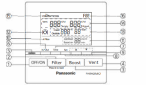
- OFF/ON Button Product standby / running
- Filter Reset Button Press the button after maintenance for resetting accumulated running time
- Boost Button Activate / Deactivate Boos Mode
- Vent Button Set supply air volume / exhaust air volume
- Boost display Light Green: Boost mode on
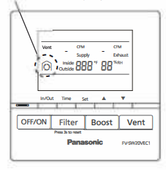
- In/Out Button Display the inside or outside temperature and humidity
- Time Button
• Set Boost time
•Set ASHRAE time - Set Button Confirm the air volume / time setting
- AY Button
•Set the air volume setting
•Set time “min. min/h - Filter Maintenance Display Display filter needs to be cleaned or changed
- ASHRAE/Boost on time Display
•Display ASHRAE time
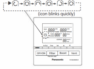
•Display Roost time - Display Defrost Mode Display the product in temperature protected- mode Air exchange: o
•Circulation: -01-A-o
Ctor anosmia. A - Display inside & outside temperature and humidity Display inside temperature and humidity Display outside temperature and humidity
- Air volume Display Display supply air volume and exhaust air volume
- COSMOS Display Display when Cosmos module is connected
- Error Code Display An error code is displayed hen the product is in failure heck troubleshooting wide for reference
OPERATION
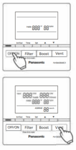
Standby mode
•Press ” I oFF/oN I”, the unit starts/standby
•The inside temperature (n°F) and humidity(%) display in
standby mode
•The unit operates in the last mode before stopping
(Note)
When connected to the wall control, the control panel of the FV-20VEC1 will be disabled. When the wall control is disconnected from the ERV,the ERV controls will be enabled.
Function mode
Air volume setting (Default: 120 CFM) G) Press” I vent I” to switch between supply air volume and exhaust air volume. f”‘lf”‘lf”‘fCFM f”‘lf”‘lf”‘fCFM C CICIO Supply � OCICI Exhaust 7
Set
Press’s=:::J” to choose and press”_. T” to adjust the volume (60, 80, 100, 120, 140, 160, 180, 200).
Press “c::==J” again to confirm the setting.
OPERATION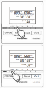
•ASHRAE time setting (Default: 60 min/h) Time CD Press the” C=::J” to change the ASH RAE time. Set
Vent BBB”” Supply BBB”” Exhaust) Press “e=::J”to choose and press “.._ T” to adjust the ,,;,, 888” 88%'” ASH RAE time (60, 50, 40, 30, 20, 10). ASHRAE 8B min/h Set ® Press”e=::J” again to confirm the setting.
(Note)
For more detailed information regarding the ASHRAE intermittent timer control, please refer to the FV-20VEC1 manual.
In/Out
• Press “C=::J” to switch temperature and humidity
between inside and outside
Defrost mode
FV–5W20VEC1
• When outdoor temperature<14 °F, ERV will enter defrost mode, defrost icon will be displayed as below.
- Heat exchange: Defrost icon display

- Circulation

- Stop operating: Defrost icon display


OPERATION
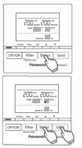
Boost mode
• Press II I Boost I II to enter boost mode, supply and exhaust air volume constant to 200 CFM.
• Boost on _time setting (Default: 20 min)
Time CD Press 11c=:J11to change the boost on time, and press 11 _.. T
to adjust (60, 50, 40, 30, 20, 10)0 Press 11c:::�:=J” to confirm the setting
• Exit boost mode:
CD Timer finishes. Press II I Boost I II again. Press II I vent I ” to set supply and exhaust air volume, thenERV will exit boost mode.
(Note)
■ Boost air volume will constant to 180 CFM when out doors temperature<14 °F.
■ For more detailed information on “Boost features and functions” please refer to the FV-20VEC1 manual
Filter reset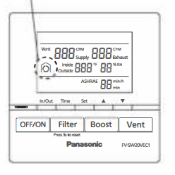 • When the filter requires cleaning, 11 ✓ Filter II will display.
•Press II I Filter I 11 3 seconds to cancel the 11 ✓ Filter II display
after filter maintenance.
(Note)
For more information on filter maintenance, please refer to the FV-20VEC1 maintenance label on the front panel.
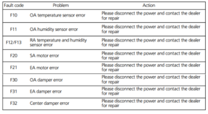
TROUBLESHOOTING
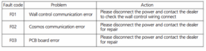
• If product is malfunctioning, a fault code will display. Please reference the following codes below.
TROUBLESHOOTING
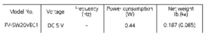
SPECIFICATIONS
PRODUCT SERVICE
Warning Concerning Removal of Covers. The unit should be serviced qualified technicians only. Your product is designed manufactured t-o ensure a minimum of maintenance. Should your unit require service or parts, call Panasonic Call Center at 1-866-292-7299 (USA) or 1-800-669-5165 (Canada). Panasonic Corporation of North America Two Riverfront Plaza, Newark, NJ 07102 www.panason1c.com Panasonic Canada Inc. 5770 Ambler Drive, Mississauga, Ontario L4W 2T3 www.panason1c.com © Panasonic Corporation 2021
download pdf
https://manuals.plus/m/8606b5308a9cd55d3df11b9ab42b211b70614b02f509dc23f781492dfb26d158_optim.pdf