

Lockly Vision PGD-829 Next-Gen Video Smart Lock Guide

Welcome!
This guide will walk you through step-by-step how to install and get your Lockly Secure Lux up and running. If you have any questions please reference our online support at: Lockly.com/support or call (669) 500-8835 for help.
Preparation
Remove the existing mortise lockset, deadbolt, or latch, and use the provided template to bore new holes.

IMPORTANT:
This product is recommended for professional installation. You may be required to use a hole saw and/or professional drilling tools to prepare the door for installation.
Configure your lockset according to your direction.
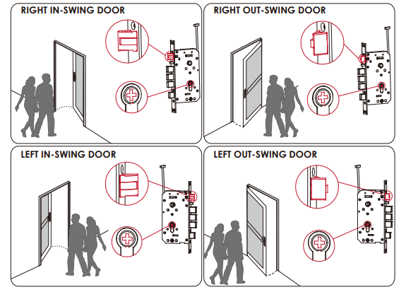
IMPORTANT:
Before installation, make sure to determine your door opening directions. This will be your reference in adjusting the latch throw, cylinder spin, and interior and exterior handles.
Change the latch throw and cylinder spin direction according to your door opening. The factory setting of the throw and cylinder spin is for the Right In-Swing door. If you have a different door opening direction, please refer to Preparation (Page 4) for the correct latch direction and spin position.
Changing latch throw direction for Right -Out Swing and Left-In Swing doors

- Use a Phillips screwdriver to remove three screws and faceplate. Rotate the latch throw to 180 °.

- Make sure the latch has fully rotated 180 ° and then re-install the faceplate.

- Secure the faceplate with 3 screws and tighten it.


Changing cylinder spin direction for Left- In Swing and Left-Out Swing Doors
- Use a Phillips screwdriver to remove the cylinder spin screw and take out the spin.

- Shift the direction of the cross hole of the spin facing the exterior for left-in swing or left-out swing door opening.

- Install the spin and secure it with screws.


INSTALLING THE LOCKSET
Install the mortise lockset into door pocket hole and tighten it with the 4 screws supplied. Route the cable inside the door pocket and place it aside.

REVERSING DOOR HANDLES
The illustrations below show how to shift the exterior and interior door handles from right to left direction. The factory setting of the handle is for a right-handed door. Skip this step if you have a right-handed door. To shift the handle from a right to a left-handed door, follow the instructions below:
Exterior Handle
- Use the allen key to remove the screw on the right (factory default screw position for right swing door)

- Use your fingers to pull the reversing barrier backward to a loosened position, then rotate the handle 180° as shown. Release the barrier to return to its original position once the handle is reversed.
- Tighten the screw on the left with the allen key.

Exterior Handle
- Remove the two screws with an Allen key.

- Push the spring hook downward and hold it with your finger. Then rotate the handle 180°.
- Lock the two screws with an Allen key.

INSTALLING THE LOCK CYLINDER
- Check door thickness and confirm if the cylinder blade needs to be cut;
- Insert the cylinder B to the cylinder hole of the exterior assembly A ;
- Secure the cylinder B to the exterior assembly A with two screws E ;
- Insert washer C on positioning rods D . Install it onto the corresponding screw hole on the exterior assembly A, and tighten it with a vise or wrench.


INSTALLING THE SPINDLE
The spindle must be inserted from the door interior passing through the lockset to the door exterior
Door Interior: The spindle must be inserted from the door interior. It must pass through completely the lockset top hole as shown below. Door Exterior: After the spindle is inserted, pull it outward by hand in the direction of the arrow, and ensure the spindle cannot be pulled out.

After the spindle is cut and installed, prepare parts I, J K & V for the exterior assembly installation

INSTALLING THE EXTERIOR ASSEMBLY
Select or adjust the escutcheon K screws (x2) according to door thickness. Install the exterior assembly, mounting plate, and escutcheon pad and secure with K screws.

Route the exterior assembly cables and rods through the corresponding holes on the lockset.

Insert the positioning sleeve into the inner side of the spindle. Make sure they are all aligned and correctly oriented. Check handles if they are in smooth operation. Then check if the locking and unlocking operations are smooth. If not, adjust the mounting plate and screws until the operation is running smoothly.
INSTALLING THE INTERIOR ASSEMBLY
- Install torque blade M to interior assembly.
- Insert the cotter pin L into the Torque Blade M according to door thickness. See notes as illustrated in the diagram.
- Remove and discard the positioning sleeve V then plug the exterior assembly cables to the corresponding socket of the interior assembly.
- Insert the torque blade into the corresponding hole and install the interior assembly onto the door. Ensure the interior assembly hole for the spindle and screw holes are aligned. Secure the interior assembly with screws N & Q

FINAL CHECK
After installation is completed, lift both the interior and exterior handles up and down making sure they are running smoothly. Then check if the deadbolts and latch are thrown smoothly with the physical keys.
INSTALLING DOOR STRIKE
Use the installation template to drill a hole in the door frame. Install the dust box S on to door frame. Then install the strike plate T and fix it with screws U.

DOWNLOAD THE LOCK APP
Congratulations! You have completed the Lockly Secure physical lock installation. To complete your setup, download the Lockly app from the App Store or on Google Play and follow the on-screen instructions.

Add more Smart to your Home
Secure Link Wi-Fi Hub
Add the optional Lockly Secure Link Wi-Fi Hub, together with the free Lockly app, it’s easier than ever to securely control and manage your door from anywhere, anytime.
Real-time, monitoring, & status
Monitor open/closed door status with real-time alerts sent to your smartphone, no matter where you are.
FCC Warning:
This device complies with Part 15 of the FCC Rules. Operation is subject to the following two conditions: (1) This device may not cause harmful interference, and (2) this device must accept any interference received, including interference that may cause undesired operation.
NOTE 1:
This equipment has been tested and found to comply with the limits for a Class B digital device, under part 15 of the FCC Rules. These limits are designed to provide reasonable protection against harmful interference in a residential installation. This equipment generates, uses, and can radiate radio frequency energy and, if not installed and used following the instructions, may cause harmful interference to radio communications.
However, there is no guarantee that interference will not occur in a particular installation. If this equipment does cause harmful interference to radio or television reception, which can be determined by turning the equipment off and on, the user is encouraged to try to correct the interference by one or more of the following measures:
NOTE 2:
Any changes or modifications to this unit not expressly approved by the party responsible for compliance could void the user’s authority to operate the equipment.
FCC Radiation Exposure Statement
The Secure Link Wi-Fi Hub complies with FCC radiation exposure limits set forth for an uncontrolled environment. It should be installed and operated with a minimum distance of 20cm between the radiator & your body.
INSTALLATION OVERVIEW & PARTS LIST

Parts List
- A Exterior Assembly
- B1 Cylinder
- B2 Keys
- C Positioning Rod Pad
- D Cylinder Positioning Rod
- E PM4 X 10mm Screw
- F Spindle
- G Lockset
- H KA4 X 25mm Screw
- I Mounting Plate
- J Escutcheon Pad
- K Escutcheon Screw
- L Cotter Pin
- M PM5 X 12mm Screw
- N Torque Blade
- O Screw Cap
- P Interior Assembly
- Q KM5 X 10mm Screw
- R Battery Cover
- S Dust Box
- T Strike Plate
- U KA4 X 18mm Screw
- V Positioning Sleeve
- W Allen Wrench
- X RFID Card
- Y Activation Card
Copyright 2022 Lockly All rights reserved
CHINA ZL 2013 1 0487970.4 | HONG KONG HK1194496 | TAIWAN 621028 | EUROPE EP3 059 689 B1 | AUSTRALIA 2013403169 | RUSSIA RU2665222 | KOREA 10-1860096 | INDONESIA IDP000064051 | Other Patents Pending The Bluetooth® word mark and logos are registered trademarks owned by the Bluetooth SIG, Inc., and any use of such marks by Lockly is under license. Other trademarks and trade names are those of their respective owners. Google, Android, Google Play, and Google Home are trademarks of Google LLC. , Amazon, Alexa, and all related logos are trademarks of Amazon.com, Inc., or its affiliates.


 Afrikaans
 Albanian
 Amharic
 Arabic
 Armenian
 Azerbaijani
 Basque
 Belarusian
 Bengali
 Bosnian
 Bulgarian
 Catalan
 Cebuano
 Chichewa
 Chinese (Simplified)
 Chinese (Traditional)
 Corsican
 Croatian
 Czech
Czech Danish
 Dutch
Dutch English
 Esperanto
 Estonian
 Filipino
 Finnish
 French
 Frisian
 Galician
 Georgian
 German
 Greek
Greek Gujarati
 Haitian Creole
 Hausa
Hausa Hawaiian
 Hebrew
 Hindi
Hindi Hmong
Hmong Hungarian
 Icelandic
 Igbo
Igbo Indonesian
 Irish
Irish Italian
 Japanese
 Javanese
 Kannada
 Kazakh
 Khmer
Khmer Korean
 Kurdish (Kurmanji)
 Kyrgyz
 Lao
Lao Latin
Latin Latvian
 Lithuanian
 Luxembourgish
 Macedonian
 Malagasy
 Malay
Malay Malayalam
 Maltese
 Maori
Maori Marathi
 Mongolian
 Myanmar (Burmese)
 Nepali
 Norwegian
 Pashto
 Persian
 Polish
 Portuguese
 Punjabi
 Romanian
 Russian
 Samoan
 Scottish Gaelic
 Serbian
 Sesotho
 Shona
Shona Sindhi
 Sinhala
 Slovak
 Slovenian
 Somali
 Spanish
 Sundanese
 Swahili
 Swedish
 Tajik
Tajik Tamil
Tamil Telugu
 Thai
Thai Turkish
 Ukrainian
 Urdu
Urdu Uzbek
Uzbek Vietnamese
 Welsh
Welsh Xhosa
Xhosa Yiddish
 Yoruba
 Zulu
Zulu