SDC 1510 Series Holding Force Emlock User Manual

INSTALLATION
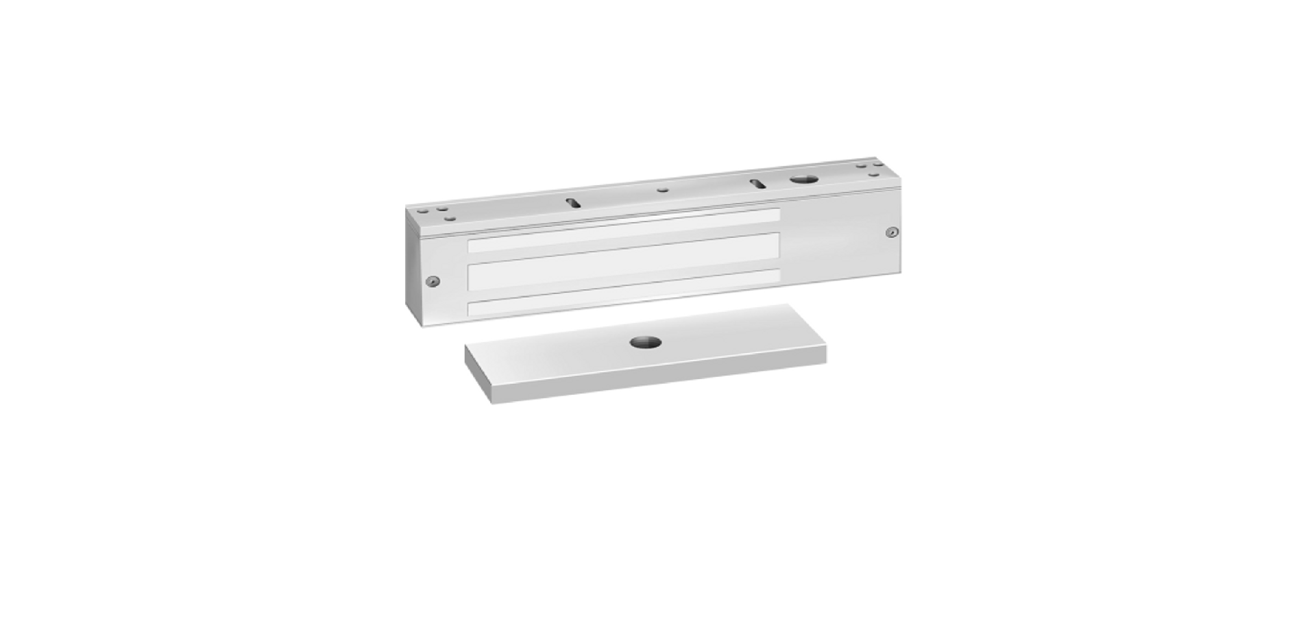
The 1500 Series Emlock is mounted to the underside of the header, on the stop side of the door. A TJ mounting kit (optional) can be used when mounting on the hinge side of the door. (Fig. 1D) The armature is mounted to the door. A hardware kit is provided to compensate for misalignment and wear of the door, by allowing the armature to pivot on it’s center point.
- Inspect the frame header to determine if an angle bracket or filler plate is required. See Figure 1A, 1B, 1C.

- Fold template as indicated by dotted line. For single doors, locate template against the door and header on the lock jamb side of the frame.
- Mark and drill holes as indicated bt template. For armature plate hole preparation, see Figure 2A, 2B, 2C.
- Mount armature to door. To determine proper hardware (provided), see Figure 2A, 2B, 2C.
- Install mounting plate to header with the interlock detail away from the door side of the stop, with #10 Flt Hd. Screws provided.

FIG. 2A HOLLOW METAL DOOR
From Sexnut side of door, drill exactly 1/2” hole thru one metal thickness only. From Armature side of door, drill 5/8” hole to insert reinforcement tube. Press in sexnut and reinforcement tube all the way and mount armature to door using hardware provided per Figure 2B.
Holding the magnet housing at each end, engage the entire length of the interlock detail, by pushing towards the door. (If necessary, tap with a soft hammer to ensure proper alignment and engagement).
Caution: The lock body must be held in place until secured with mounting screws. Screws provided inside the housing at each end. Tighten the screws and check alignment.7. Test operation. When all is operating properly, tighten all screws. Install anti-tamper plugs over socket head screw using a soft hammer to avoid damage to the housing. Electromagnet and armature should be handled carefully. Any damage to the surface such as paint, burrs, dirt and rust may hinder bonding of surface and reduce holding power.
SHOULD THE SURFACE PLATING BE DAMAGED: Do not touch the lock face with your hands. Using a soft, clean, dry cloth or abrasive cloth (i.e., Scotch-Brite), clean lock face. Do not use sand paper. A rust inhibitor such as M1, manufactured by Starret, or LPS3, manufactured by LPS Laboratories (available at most hardware stores) can then be applied. Apply a coat of inhibitor to armature face also

Drill 3/8” hole thru door. From sexnut side of door, drill exactly 1/2” hole, 1-3/8” deep. Mount armature to door with hardware provided per Figure 2A.

FIG. 2C REINFORCED DOORDrill and tap for 5/16-18 machine screw. Mountarmature to door with hardware provided per Figure 2C.
ELECTRICAL SPECIFICATIONS
SERIES
INPUT VOLTAGE (VDC)
POWER CONSUMPTION (mA)
COIL RESISTANCE (OHMS)
HOLDING FORCE (LBS)
1510
12/24
700/350
1650
35 (PER COIL) * 12/24250/1251200100 (PER COIL) * 158012/24440/220 65060 (PER COIL)
NOTE: For a proper coil resistance reading, turn off the DC voltage. Use an ohmmeter and measure the resistance between the pins of the plug connector positions E1-E2 and E3-E4
REFRENCE LINK
https://www.sdcsecurity.com/1570-Series-1200lb-Holding-Force-EMLocks.htm


