SDC Low Energy Swing Door Automatic Operator User Manual

PRODUCT DESCRIPTION & SPECIFICATIONS
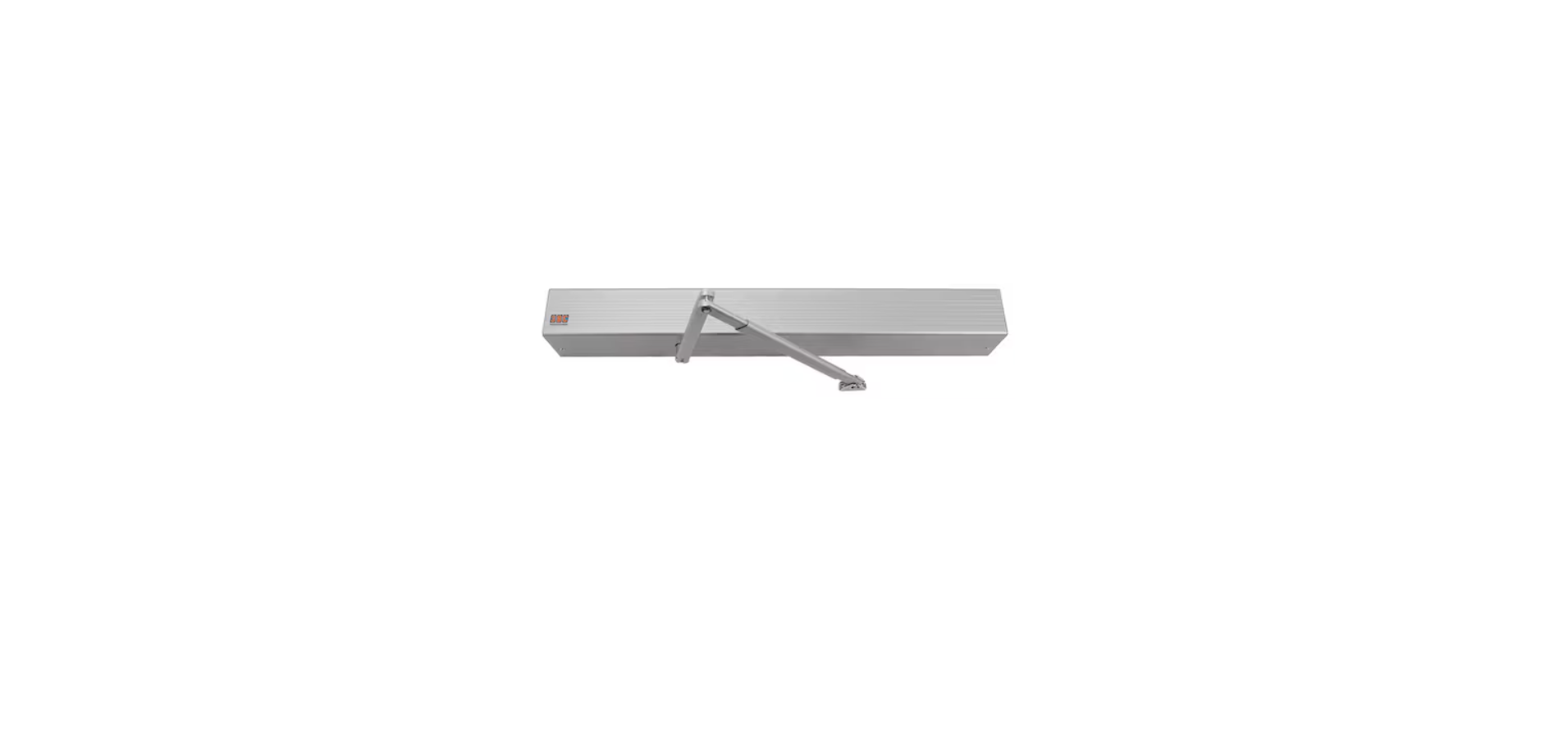
The SDC Auto EntryControl™ Low Energy Swing Door Operator provides safe and reliable point of entry door control featuring a state‐of‐the‐art microprocessor‐based controller with electro‐mechanical drives. The unit is self‐tuning and self‐learning while offering non‐handed operation, full mechanical stops, and a variety of interface options for sensors, push‐plates, fire alarms, and electrified locks. A versatile, slim‐line design makes it suitable for surface mounted (push/pull) applications.
Power Supply 115 VAC (+6%, ‐10%) 60Hz
Power Consumption 100W
Current Consumption 1A
Motor 24 VDC Permanent Magnet With Belt Driven Encoder
Header Dimensions 4‐1/2” x 4‐7/8” (l x w x d);
length: 39”/45”/51” for 36”/42”/48” opening, respectively
Fused Protection 3.5A Fuse (“F1” located on I/O Board)
Motor Assembly Weight 22 lbs. Per Operator Drive Assembly
Ambient Operating Temperature ‐4° to 131° F
Ingress Protection IP23 (protection from spray water up to 60° from vertical)
Maximum Door Weight PUSH ARM PULL ARM
36” Door: 438 lbs. 342 lbs.
42” Door: 328 lbs. 256 lbs.
48” Door: 254 lbs. 198 lbs.
24 VDC Accessories/Lock Power Supply 24 VDC / 1A max.
Adjustable Speeds & Timers Potentiometers Auto Opening Speed
Auto Closing Speed
Hold Open Time
Closing Speed w/ Power Off
External Selector Switch Functions Automatic
Hold Open
Manual (Off/Night)
Standard Control Outputs 24 VDC Power Supply
Lock Relay
Door Status (Fully Open and Fully Closed)
Malfunction Alarm Signal
Standard Control Inputs Interior Activation
Exterior Activation
Emergency Shutdown
Fire Alarm Input
Secondary Activation (Push side door mounted presence sensor)
Stop Safety Device Input (Pull side presence sensor)
STEP 1: HEADER BACKPL $ATE INSTALLATION

- Remove the header front cover by removing the 4 hex screws on the top & bottom of the operator.
- The motor assembly is factory mounted to the slotted back plate using FIVE hex bolts.
- The bolts attach to nuts that slide in the two slotted tracks of the back plate.
- The motor assembly should be removed before installing the housing backplate.
NOTE: When you order a PULL or PUSH operator, the motor assembly will be shipped from the factory in the appropriate PULL or PUSH orientation. Take note of the orientation before removing the motor assembly (i.e. Is the motor towards the center of the housing, or the edge of the housing)

To remove the motor assembly: First, remove the single hex bolt and washers located behind the transformer (a ball end hex wrench is recommended). Disconnect the ON‐Auto‐OFF connector from the board and unplug the molex main power connector.

Next, locate & loosen the 4 side hex bolts (see below). NOTE: One of the four hex bolts is fastened to the green ground wire of the power connector. This bolt will need to be removed temporarily to disconnect the green wire. Slide the bolts away from the motor assembly allowing the assembly to be removed.

Determine the handing of the door

The backplate will mount with the edge nearest the spindle cutout towards to the hinge

Mount the backplate to the top door frame using 5 or 6 of the screws provided, or use appropriate fasteners for the type of frame. Install reinforcement as required.

- Push side mounting: Bottom of the backplate is flush with bottom of the door frame. For hollow metal applications, drop 1/8”below the frame.
- Pull side mounting: Bottom of the backplate is mounted 1.5” up from bottom door frame.
- For a 36” opening, backplate should overlap each hinge jamb tube by 1.5”.
- Refer to the APPENDIX for fire rated door applications.

PUSH‐ARM APPLICATIONS: Bottom of operator header is flush with bottom of top frame.
NOTE: A 35 mm spindle adaptor is included with all standard push arm applications. This requires that the header assembly be mounted as shown at left, flush with bottom of frame face.

PULL ARM APPLICATIONS: Bottom of operator is mounted 1.5” up from the bottom side of top door frame Backplate should overlap hinge jamb tube by 1.5” (See figure below)

STEP 2: RE-MOUNT THE MOTOR ASSEMBLY
The orientation of the motor assembly will depend on the door handing & application (see below).
PUSH APPLICATION (I/O board towards the hinge)

Before reinstalling the motor, take notice of the location of the 4 mounting hex bolts, and the nut for the 5th mounting bolt

- Place and Hold the motor assembly up to the header, allowing it rest on the slotted tracks.
- Slide in the 4 outer hex bolts and tighten loosely. Slide the entire assembly left or right to line up the 5th hex bolt nut with the mounting hole from the bolt removed on page 5 (near the transformer). Reinsert the hex bolt and washers removed on page 5.
- Temporarily remove one of the mounting hex bolts and washers from the I/O board side of the assembly to allow the ground wire ring connector to be reconnected.
- After all 5 hex bolts have been inserted, reposition the whole assembly so that the spindle attachment point is centered with the spindle cutout, as shown on the bottom of page 5. Secure the motor assembly by tightening all 5 hex bolts.
- Reconnect the ON‐Auto‐OFF connector to the I/O board and the molex main power connector.
STEP 3: INSTALL THE ARM ASSEMBLY – STANDARD APPLICATION
NOTE: All operator arms include a standard spindle as shown below. Arm assembly options are detailed on the next three pages. Proceed to Page 14 for arm installation instructions.
PUSH ARM FOR STANDARD PUSH APPLICATION FOR REVEALS UP TO 8”

PULL ARM FOR STANDARD PULL APPLICATION WITH 0” REVEAL
NOTE: FOR REVEALS > 0” BUT LESS THAN ½”, A SPACER (PROVIDED BY INSTALLER) MAY BE INSTALLED BEHIND THE SLIDE TRACK TO ACHIEVE A 0” REVEAL. FOR A PULL APPLICATION WITH A REVEAL GREATER THAN ½”, USE A DOUBLE EGRESS ARM WITH A 20mm SPINDLE.

DOUBLE EGRESS ARM FOR STANDARD DOUBLE EGRESS PAIR OF DOORS, OR FOR A PULL APPLICATION WITH A REVEALGREATER THAN ZERO INCHES
NOTE: AN 80mm SPINDLE IS INCLUDED WITH THE DOUBLE EGRESS ARM. THE 80mm SPINDLE SHOULD BE USED FOR DOUBLE EGRESS PAIR OF DOORS. FOR PULL APPLICATIONS WITH REVEALS > 0”, USE A DOUBLE EGRESS ARM WITH A 20mm SPINDLE (SOLD SEPARATELY).
REFRENCE LINK


 Afrikaans
 Albanian
 Amharic
 Arabic
 Armenian
 Azerbaijani
 Basque
 Belarusian
 Bengali
 Bosnian
 Bulgarian
 Catalan
 Cebuano
 Chichewa
 Chinese (Simplified)
 Chinese (Traditional)
 Corsican
 Croatian
 Czech
Czech Danish
 Dutch
Dutch English
 Esperanto
 Estonian
 Filipino
 Finnish
 French
 Frisian
 Galician
 Georgian
 German
 Greek
Greek Gujarati
 Haitian Creole
 Hausa
Hausa Hawaiian
 Hebrew
 Hindi
Hindi Hmong
Hmong Hungarian
 Icelandic
 Igbo
Igbo Indonesian
 Irish
Irish Italian
 Japanese
 Javanese
 Kannada
 Kazakh
 Khmer
Khmer Korean
 Kurdish (Kurmanji)
 Kyrgyz
 Lao
Lao Latin
Latin Latvian
 Lithuanian
 Luxembourgish
 Macedonian
 Malagasy
 Malay
Malay Malayalam
 Maltese
 Maori
Maori Marathi
 Mongolian
 Myanmar (Burmese)
 Nepali
 Norwegian
 Pashto
 Persian
 Polish
 Portuguese
 Punjabi
 Romanian
 Russian
 Samoan
 Scottish Gaelic
 Serbian
 Sesotho
 Shona
Shona Sindhi
 Sinhala
 Slovak
 Slovenian
 Somali
 Spanish
 Sundanese
 Swahili
 Swedish
 Tajik
Tajik Tamil
Tamil Telugu
 Thai
Thai Turkish
 Ukrainian
 Urdu
Urdu Uzbek
Uzbek Vietnamese
 Welsh
Welsh Xhosa
Xhosa Yiddish
 Yoruba
 Zulu
Zulu