State Water Heaters Residential Side Plumbing Electric Water Heaters User Guide

General Safety
WARNING
At the time of manufacture this water heater was provided with a combination temperature-pressure relief valve
certified by a nationally recognized testing laboratory that maintains periodic inspection of production of listed equipment or materials, as meeting the requirements for Relief Valves and Automatic Gas Shutoff Devices for Hot
Water Supply Systems, and the latest edition of ANSI Z21.22 and the code requirements of ASME. If replaced,
the valve must meet the requirements of local codes, but not less than a combination temperature and pressure
relief valve certified as meeting the requirements for Relief Valves and Automatic Gas Shutoff Devices for Hot
Water Supply Systems, ANSI Z21.22 by a nationally recognized testing laboratory that maintains periodic inspection of production of listed equipment or materials HAZARD OF ELECTRICAL SHOCK! Before removing any access panels or servicing the water heater, make sure the electrical supply to the water heater is turned “OFF”. Failure to do this could result in DEATH, SERIOUS BODILY INJURY, OR PROPERTY DAMAGE.
Preparing for the New Installation
- Read the “General Safety” section on page 2 of this manual first and then the entire manual carefully. If you don’t follow the safety rules, the water heater will not operate properly. It could cause DEATH, SERIOUS
BODILY INJURY AND/OR PROPERTY DAMAGE. - The installation must conform with the instructions in this manual; electric company rules; and Local Codes, or in the absence of Local Codes, with the latest edition of the National Electrical Code.
- If after reading this manual you have any questions or do not understand any portion of the instructions, call the manufacturer whose name appears on the rating plate.
- Carefully plan the place where you are going to put the water heater. Correct electrical wiring and connections
are very important in preventing death from possible electrical shock and fires. Examine the location to ensure the water heater complies with the “Locating the New Water Heater” section. - For California installation this water heater must be braced, anchored, or strapped to avoid falling or moving during an earthquake. See instructions for correct installation procedures. Instructions may be obtained from your local dealer, wholesaler, public utilities or California Office of the State Architect, 400 P Street,
Sacramento, CA 95814. - Massachusetts Code requires this water heater to be installed in accordance with Massachusetts 248-CMR 2.00: State Plumbing Code and 248-CMR 5.00
Locating the New Water Heater
Facts to Consider About the Location
You should carefully choose an indoor location for the new water heater, because the placement is a very important consideration for the safety of the occupants in the building and for the most economical use of the appliance. This water heater is not intended for outdoor installation. Whether replacing an old water heater or putting the
water heater in a new location, the following critical points must be observed.
- The location selected should be indoors as close to and as centralized with the water piping system as possible.
This water heater, as well as all water heaters, will eventually leak. Do not install without adequate drainage provisions where water flow will cause damage. - The location selection must provide adequate clearances for servicing and proper operation of the water heater.
CAUTION
- WATER HEATERS EVENTUALLY LEAK: Installation of the water heater should be accomplished in such a manner that if the tank or any connections should leak, the flow of water will not cause damage to the structure. For this reason, it is not advisable to install the water heater in an attic or upper floor.
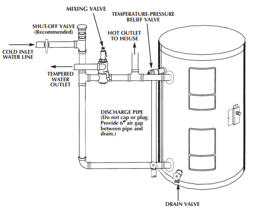
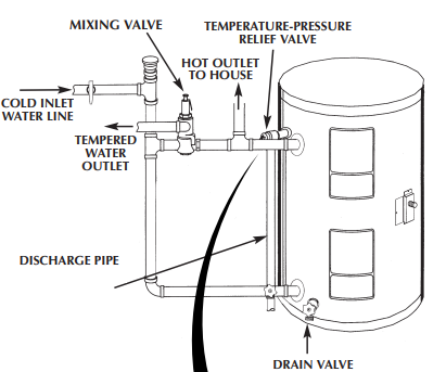
Typical Installation
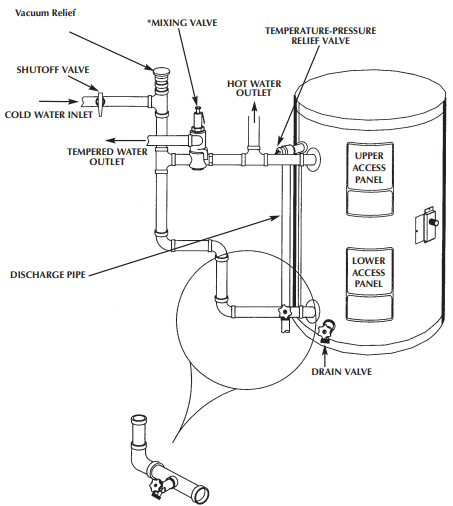
NOTE: To protect against untimely corrosion of hot and cold water fittings, it is strongly recommended that dielectric unions or couplings be installed on this water heater when connected to copper pipe.
Installing the New Water Heater
Water Piping
If a water heater is installed in a closed water supply system; such as one having a back-flow preventer, check valve, water meter with a check valve, etc… in the cold water supply; means shall be provided to control thermal expansion.
Contact the water supplier or plumbing contractor on how to control this situation. The illustration shows the attachment of the water piping to the water heater. The water heater is equipped with 3 ⁄4 inch water connections .
NOTE: If using copper tubing, solder tubing to an adapter before attaching the adaptor to the cold water inlet connection. Do not solder the cold water supply line directly to the cold water inlet. It will harm the dip tube and damage the tank.
Temperature-Pressure Relief Valve
WARNING
The temperature-pressure relief valve must be manually operated at least once a year. Caution should be taken to ensure that no one is in front of or around the outlet of the temperature-pressure relief valve discharge line, and
the water manually discharged will not cause any bodily injury or property damage because the water may be extremely hot. If after manually operating the valve, it fails to completely reset and continues to release water, immediately close the cold water inlet to the water heater, follow the draining instructions, and replace the temperature-pressure relief valve with a new one.
NOTE: To protect against untimely corrosion of hot and cold water fittings, it is strongly recommended that dielectric unions or couplings be installed on this water heater when connected to copper pipe.
Filling the Water Heater
To fill the water heater with water:
- Close the water heater drain valve by turning the handle to the right (clockwise). The drain valve is on the lower front of the water heater.
- Open the cold water supply valve to the water heater.
- To insure complete filling of the tank, allow air to exit by opening the nearest hot water faucet. Allow water to
run until a constant flow is obtained. This will let air out of the water heater and the piping.
CAUTION: Never use this water heater unless it is completely full of water. To prevent damage to the tank and heating element, the tank must be filled with water. Water must flow from the hot water faucet before turning “ON” power
Wiring
You must provide all wiring of the proper size outside of the water heater. You must obey local codes and electric company requirements when you install this wiring. If you are not familiar with electric codes and practices,
or if you have any doubt in your ability to connect the wiring to this water heater, obtain the service of a competent electrician. Contact a local electrical contractor and/or the local electric utility.
- Provide a way to easily shut off the electric power when working on the water heater. This could be with a circuit breaker or fuse block in the entrance box or a separate disconnect switch.
- Install and connect a circuit directly from the main fuse or circuit breaker box. This circuit must be the right size and have its own fuse or circuit breaker.

Temperature Regulation
Thermostats
ADJUSTABLE UPPER THERMOSTAT BEHIND UPPER ACCESS PANEL (DUAL ELEMENT MODELS ONLY) The lower thermostat is factory set at a position which approximates 120°F (HOT) and is adjustable if a different water temperature is desired. Read all warnings in this manual and on the water heater before proceeding.

Thermostat Adjustment
On dual element models, both the upper and lower thermostats have been factory set at HOT (approximately
120°F) to reduce the risk of scald injury. The upper and lower thermostats are adjustable if a different water temperature is desired. Read all warnings in the “Temperature-Regulation” section before proceeding. To adjust the temperature setting for both upper and lower thermostats:
- Turn “OFF” the electrical power to the water heater at the junction box.
Periodic Maintenance
Temperature-Pressure Relief Valve Operation
The temperature-pressure relief valve must be manually operated at least once a year.

Failure to install and maintain a new properly listed temperature-pressure relief valve will release the manufacturer from any claim which might result from excessive temperature or pressure.
Draining
Also periodic draining and cleaning of sediment from the tank may be necessary.
- Before beginning turn “OFF” the electric power supply to the water heater.
- CLOSE the cold water inlet valve to the water heater.
- OPEN a nearby hot water faucet and leave open to allow for draining.
- Connect a hose to the drain valve and terminate to an adequate drain or outdoors.
- OPEN the water heater drain valve to allow for tank draining.
- Close the drain valve.
- Follow “Filling the Water Heater” instructions in the “Installing the New Water Heater” section.
- Turn “ON” power to the water heater
Leakage Checkpoints
Use this guide to check a “Leaking” water heater. Many suspected “Leakers” are not leaking tanks. Often the source of the water can be found and corrected. If you are not thoroughly familiar with electric codes, the water heater, and safety practices, contact a local electrical contractor and/or the local electric utility to check the water heater.

A.Condensation may be seen on pipes in humid weather or pipe connections may be leaking
B. Small amounts of water from temperature-pressure relief valve may be due to thermal expansion or high water pressure in your area.
C.The temperature-pressure relief valve may be leaking at the tank fitting.
D.The elements may be leaking at the tank fitting. Turn electrical power “OFF”, remove access panels and fold back insulation. If leaking around elements, follow proper draining instructions and remove element. Reposition or replace gasket on element. Place element into opening and tighten securely. Then follow “Filling the Water Heater” instructions in the “Installing the New Water” section.
E.Water from a drain valve may be due to the valve opened slightly. Note: Only 30 gallon model is
equipped with a drain valve.
F. The drain valve may be leaking at the tank fitting.
G. Water in the water heater bottom or on the floor may be from condensation, loose connections or the temperature-pressure relief valve. DO NOT replace the water heater until a full inspection of all possible water sources is made and necessary corrective steps taken. Leakage from other appliances, water lines, or ground seepage should also be checked.
CAUTION
Never use this water heater unless it is completely full of water. To prevent damage to the tank and heating element,
the tank must be filled with water. Water must flow from the hot water faucet before turning “ON” power.
Notes:
To check where threaded portion enters tank, insert cotton swab between jacket opening and fitting. If cotton is wet, follow “Draining” instructions in the “Periodic Maintenance” section and then remove fitting. Put pipe dope or teflon tape on the threads and replace. Then follow “Filling the Water Heater” instructions in the “Installing the New Water Heater” section.
Repair Parts

- Element Gasket
- Element (Upper and Lower)
- Thermostat Bracket
- Upper Thermostat w/Hi Limit
- Terminal Cover
- Access Panel
- Lower Thermostat w/4 Pole Hi Limit
- 2 Pole Thermostat
- Inlet Nipple
- Hot Outlet Assembly
- T&P Valve
- Conduit Bracket
- Junction Box Cover
- Drain Valve (30 gal. model only


 Afrikaans
 Albanian
 Amharic
 Arabic
 Armenian
 Azerbaijani
 Basque
 Belarusian
 Bengali
 Bosnian
 Bulgarian
 Catalan
 Cebuano
 Chichewa
 Chinese (Simplified)
 Chinese (Traditional)
 Corsican
 Croatian
 Czech
Czech Danish
 Dutch
Dutch English
 Esperanto
 Estonian
 Filipino
 Finnish
 French
 Frisian
 Galician
 Georgian
 German
 Greek
Greek Gujarati
 Haitian Creole
 Hausa
Hausa Hawaiian
 Hebrew
 Hindi
Hindi Hmong
Hmong Hungarian
 Icelandic
 Igbo
Igbo Indonesian
 Irish
Irish Italian
 Japanese
 Javanese
 Kannada
 Kazakh
 Khmer
Khmer Korean
 Kurdish (Kurmanji)
 Kyrgyz
 Lao
Lao Latin
Latin Latvian
 Lithuanian
 Luxembourgish
 Macedonian
 Malagasy
 Malay
Malay Malayalam
 Maltese
 Maori
Maori Marathi
 Mongolian
 Myanmar (Burmese)
 Nepali
 Norwegian
 Pashto
 Persian
 Polish
 Portuguese
 Punjabi
 Romanian
 Russian
 Samoan
 Scottish Gaelic
 Serbian
 Sesotho
 Shona
Shona Sindhi
 Sinhala
 Slovak
 Slovenian
 Somali
 Spanish
 Sundanese
 Swahili
 Swedish
 Tajik
Tajik Tamil
Tamil Telugu
 Thai
Thai Turkish
 Ukrainian
 Urdu
Urdu Uzbek
Uzbek Vietnamese
 Welsh
Welsh Xhosa
Xhosa Yiddish
 Yoruba
 Zulu
Zulu