Kepco ATE-DMG Series Stabilized Power Supply User Manual

INTRODUCTION
SCOPE OF MANUAL
This Quick Start Guide covers simple installation and local operation of the Kepco ATE-DMG Series of 1000W voltage and current stabilized
d-c power supplies. Full specifications, features and instructions are found in the associated Operator Manual that can be downloaded free from the Kepco web site at: www.kepcopower.com/support/opmanls.htm#ate-dmg
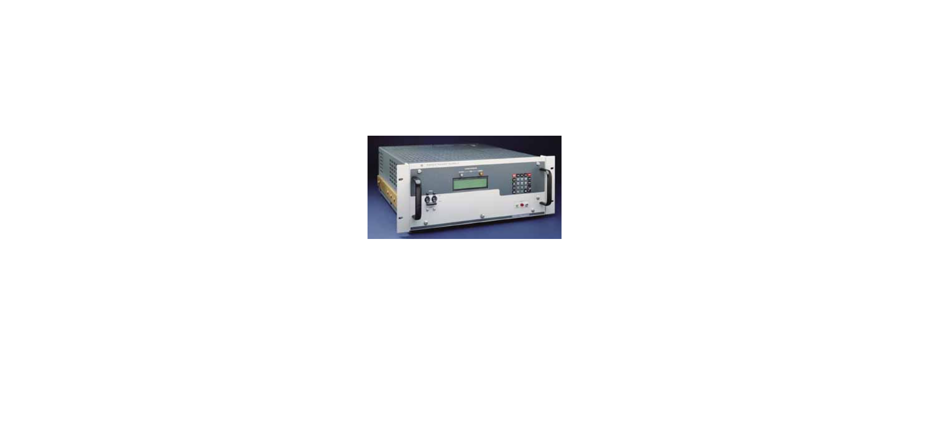
DESCRIPTION
The Kepco ATE-DMG with programmable overvoltage protector is a precision stabilized power supply which can deliver either stabilized output voltage or current. The prevailing operating mode is indicated by LED mode indicators on the front panel. Operating mode crossover is automatic and may be monitored remotely by commands provided via the GPIB port. A digital front panel display shows the output voltage and output current. This power supply has a linear and fully dissipative NPN pass transistor section driven by high-gain, integrated circuit
amplifiers. The output of the power supply is fully programmable via either the GPIB port or the front panel keypad or from an external analog reference when enabled from the front panel menu. Terminals are also provided for remote error sensing, as well as for the connection of the output capacitor directly at the load. The ATE-DMG power supply features user-selectable “slow” or “fast” operating modes. Slow mode operation is recommended for applications demanding a constant voltage source. Fast mode operation is best if the output voltage must change rapidly, either in response to an external programming signal or, if the ATE-DMG is used as a current stabilizer. The ATE-DMG power supply is delivered for “slow mode” operation. Refer to Operator Manual (see PAR. 1.1) for converting the ATE-DMG power supply to “fast mode” operation. A continuously adjustable overvoltage protection circuit is a built-in feature. The trigger point of the overvoltage protector may be set (or checked) under actual operating conditions by the front panel accessible setup controls. Units are shipped for 115V a-c operation (105V to 125V a-c), 47 to 63Hz. For operation at 104V a-c, 208V a-c or 230V a-c refer to the full Operator Manual (see PAR 1.1).
SAFETY.
Exercise care in making all connections to and from the ATE-DMG terminals. There are no operator serviceable parts inside the case
WARNINGS
- Remove a-c power from the ATE-DMG before making any connections.
- Wires and/or cables, connected from the ATE-DMG terminals to external components or programming devices must be properly insulated and securely terminated on both sides to make accidental touch impossible.
- The ATE-DMG chassis and cover must be safetygrounded to a reliable a-c source ground. A safetyground may be established by using the power cord supplied with a grounded a-c power outlet or, if the latter is not available, by means of a separate wire, from the provided GROUND terminal (at the rear barrier strip) to a reliable a-c source ground point.
EQUIPMENT SUPPLIED.
- 115V a-c Line Cord terminated with NEMA 5-20P plug.
ACCESSORIES (NOT SUPPLIED)
IEEE 488 Cables to connect ATE-DMG power supply to GPIB bus (1, 2 or 4 meters long) are available. See Operator Manual for complete list of accessories.

INSTALLATION
UNPACKING
The power supply has been thoroughly inspected and tested prior to packing and is ready for operation. After careful unpacking, inspect for shipping damage before attempting to operate. Perform the Preliminary Checkout (PAR. 3.2). If any indication of damage is found, file an immediate claim with the responsible transport service
PRELIMINARY CHECKOUT
A simple operating check after unpacking and before permanent installation, is advisable to ascertain whether the ATE-DMG has suffered damage in shipment.
- Refer to Safety instructions (see Section II) and connect unit to 115V a-c source; refer to Operator Manual (see PAR 1.1) for different source voltage.
- With POWER switch set to off position, connect the power supply to source power.
- With no load connected, set POWER switch to ON. Each time the unit is turned on an internal self-test is performed. If the test is successful the following indications are visible:
- The alphanumeric display (LCD) indicates the model and GPIB address.
- After approximately 2 seconds, the display changes to the power on default values: Local mode, Constant Voltage (CV) mode, 0.000V, 0.000A, output disabled, command entry status (see Figure 2).

NOTE: means blinking colon (:) indicating Command Entry status means blinking equal sign (=) indicating Data Entry status
- Overcurrent and Overvoltage protection are set to the maximum values (see Operator Manual, PAR. 1.1), but are not displayed.
NOTE: Six keys with dual functions are labeled with both a command and a number. The command label is referred to when the unit is in command entry status; the number is referred to when the unit is in data entry status.
- Press OUTPUT ON/OFF key to enable the output.
- Connect a digital voltmeter (DVM) to the (+) and (–) terminals at the rear panel and verify DVM reads 0V.
- Press V SET key. Verify bottom line of LCD reads Vset nn (where nn = voltage setting).
- Use number keys to enter rated maximum voltage (e.g. for ATE 25-40DMG, 25V is the rated maximum voltage) and press ENTER. Output voltage will be displayed at bottom left of LCD.
- Use keys as necessary to adjust output precisely to rated maximum voltage. Verify DVM voltage reading agrees with displayed voltage on LCD within 0.01% of rated maximum. If the LCD reads VsetMAX= (value), you are entering a value higher than the maximum voltage setting
INSTALLING THE POWER SUPPLY
ATEDMG is intended to be rack-mounted; the four bottom feet must be removed prior to installation. Refer to PAR. 3.5 for cooling requirements.
CONNECTIONS. Connections are made using the rear panel terminations (see Figure 4).
LOAD CONNECTION, GENERAL
- Connect the load between –OUT and +OUT output terminals at the rear panel (see Figure 4. Sense connections are required, either local or remote, must be used; otherwise the unit will not operate.
- See PAR. 3.4.2 for local sensing, see PAR. 3.4.3 for remote sensing. “Fast” mode is recommended if step changes in the load are expected: if, for example, the load is rapidly changing in value, or if the power supply is programmed with step functions (square wave, pulse, etc.) and maximum dynamic performance is expected. Set the unit to “fast” mode by referring to the full Operator Manual (see PAR. 1.1). Note that ripple in “fast” mode will be higher than for the default “slow” mode.
- Terminals on the barrier strip permit maximum flexibility in power supply/load interface techniques. The unit is shipped with several jumper links installed (see Figure 3) for the default configuration: front panel (local) control of output voltage, output current and VP crowbar level with the power supply operating in the “slow” mode. Links on the barrier strip must be tightened. CAUTION: Loose links at the barrier strip will cause malfunction of the power supply.
- To configure the unit to allow remote programming of the power supply or for “fast mode,” refer to the full Operator Manual (see PAR. 1.1).
LOAD CONNECTION, LOCAL SENSING
Figure 3 illustrates load connection using local sensing. Refer to the full Operator Manual (see PAR. 1.1) for load wire selection guidelines. The output power leads should be twisted or tied together to reduce EMI.

LOAD CONNECTION, REMOTE SENSING
To avoid excessive output effects at remote loads, remote error sensing must be used (Kelvin connection). A pair of wires (twisted to reduce EMI) connected from the sensing terminals directly to the load will compensate for load wire voltage drops up to 0.5 volt per wire (refer to Figure 4. Observe polarities: the negative sensing wire must go to the negative load wire, and the positive sensing wire goes to the positive load wire. If step changes in the load are expected (e.g., the load is rapidly changing in value and maximum dynamic performance is expected directly at the load terminals, refer to the full Operator Manual (see PAR. 1.1) for alternative remote sensing connections. For large capacitive loads with long wire runs, refer to the full Operator Manual (see PAR. 1.1) for techniques used to reduce low frequency oscillations observed at the load.

INPUT A-C CONNECTIONS
Install the line cord (supplied) at the rear panel and connect to 115V a-c, 60Hz (105V to 125V a-c, 50 to 65Hz) mains. Refer to the full Operator Manual for operation at 104V a-c, 208V a-c or 230V a-c (see PAR. 1.1).
A-C SAFETY GROUND
The power supply is equipped with a 3-wire safety line cord and polarized plug. The third (green) wire in the line cord is connected to the chassis and the case of the unit. If a 2-terminal receptacle in combination with an adapter is used, it is imperative that the chassis of the power supply be returned to a-c ground with a separate lead. A grounding terminal is provided (at the rear barrier strip) for this purpose.
ISOLATION FROM GROUND
The d-c output is isolated from the a-c source and from any direct connection to chassis or ground. The maximum output voltage that can be supported between either output terminals and chassis ground is 500V (d-c or peak). Either side of the output may be grounded. A resistor/capacitor network is connected from the negative monitor terminal to the metal chassis of the power supply. If this internal network is not desired, the connection to the chassis can be opened by removing the link (8)-(9) on the rear panel barrier strip TB201 (see Figure 4).

COOLING
The components in the ATE-DMG power supply rely on forced air cooling. CAUTION: SIDE PANEL AND REAR PANEL OPENINGS AND THE TOP OF THE CASE MUST BE KEPT CLEAR FROM ALL OBSTRUCTIONS TO ENSURE AIR CIRCULATION. Periodic cleaning of the interior of the power supply is recommended. When the ATE-DMG is rack-mounted or installed into confined spaces, care must be taken that the ambient temperature (the temperature immediately surrounding the power supply) does not rise above 50°C (~122°F). Derate power by 10% if ambient temperature exceeds 55°C (~131°F).
OPERATION
Turn the unit on using the front panel a-c POWER ON/OFF switch/circuit breaker (see CAUTION, PAR. 4.3). The ATE-DMG power supply is delivered for “slow mode” operation (see PAR. 1.2). Refer to full Operator Manual (see PAR. 1.1) for converting the ATE-DMG power supply to “fast mode” operation.
OVERVOLTAGE CROWBAR SETUP AND CHECK
The overvoltage crowbar circuit protects the load from momentary or long-term overvoltages. The crowbar SCR conducts across the power supply output, and the a-c power switch/circuit breaker is tripped if overvoltages occur. The front panel LEVEL control determines the threshold between the actual operating voltage of the power supply and the level at which the crowbar circuit will be activated. The LEVEL control can be set from 3 volts to 110% of the rated output voltage. The LEVEL control may be adjusted very close to the operating voltage (minimum threshold = 2% of rated output voltage or 0.5 volt, whichever is greater). The operation of the crowbar circuit can be checked as follows without actually triggering the crowbar. All operating controls are accessible at the front panel (see Figure 1).
- Without connecting the load to the power supply turn Crowbar LEVEL control fully clockwise.
- Turn a-c POWER switch/circuit breaker on. Press V SET key, then use the keypad to enter the desired value at which the crowbar must trigger (NOT the actual operating voltage), then press ENTER.
- Depress the DISABLE button (and keep it depressed) white turning the LEVEL control counterclockwise, until the CROWBAR indicator energizes (simulated crowbar action).
- With the DISABLE button still depressed, press V SET key, then use the keypad to enter the actual operating voltage and press ENTER key. Release the DISABLE button.
NOTE: This last adjustment established the threshold, i.e., the difference voltage between the output voltage and the voltage at which the power supply will crowbar. For minimum false triggering use the largest threshold your load can tolerate.
- To check the adjusted crowbar trigger level, depress DISARM push button. Press V SET key, then use the keypad to enter the voltage trip point, minus 1%, then press ENTER.
- Depress the key and note the voltage at which the CROWBAR indicator lamp energizes. Correct LEVEL adjustment as described above if necessary. Use V SET to reduce power supply output voltage to its operating value.
NOTE: Readjustment of the LEVEL control may be required after load and power supply have reached thermal equilibrium.
- If an exact crowbar point at a remote load must be established, remote error sensing, as described in PAR. 3.4.3 must be used.
LOCAL MODE (KEYPAD) OPERATION
The front panel keypad is comprised of 24 key, 13 dedicated to command functions, 5 dedicated to data functions, and 6 keys that have both command and data functions When the power supply is in command entry status the command functions are effective; when the power supply is in data entry status the data functions are effective.
COMMAND ENTRY STATUS
Indicated by a blinking colon (:) on the bottom line of the LCD. The power supply is waiting for a command to be entered; data will not be accepted (accompanied by brief audible buzz). The LCD indicates the actual voltage and current at the output terminals. When the output is disabled (LCD bottom line reads Output OFF), the power supply is in Command entry status even though the blinking colon is not visible.
NOTE: Blinking colon is indicated by in this manual.
DATA ENTRY STATUS
Entered automatically when data entry required. Indicated by blinking equal sign (=) on bottom line of LCD; the power supply is waiting for data to be entered. A command will not be accepted (accompanied by brief audible buzz). Enter new value (the key erases data entered). Press ENTER to accept new setting, or CLEAR to exit without changing setting.
NOTE: Blinking equal sign is indicated by in this manual.
DISPLAY (LCD)
The LCD is a 2-line display with a capacity of 16 characters per line. The information is generally arranged as follows (information that does not follow this format is self-explanatory): At top left: Loc/Rem indicates Local or Remote status. At top right: CV/CC indicates Constant Voltage or Constant Current mode. At bottom left: n.nnnV indicates output voltage if in command entry or (parameter) (e.g. OVset if OV SET key was pressed) if in data entry. Bottom middle shows (blinking “:”) for command entry or (blinking “=”) for data entry. At bottom right: n.nnnA indicates output current in command entry, or, in data entry, n.nnn indicates the present value of the parameter indicated at the bottom left (the present value is replaced by data entered).
KEYPAD FUNCTIONS
(Refer to Figure 1.) Six keys have dual functions, depending on whether the power supply is in command entry status (waiting for a command to be entered), or data entry status (waiting for a number to be entered). Command entry status is indicted on the LCD by a blinking colon and data entry status is indicated by a blinking equal sign .
NOTE: Keys with dual functions are labeled with both a command and a number. The command label is referred to when the unit is in command entry status; the number is referred to when the unit is in data entry status.
- OUTPUT ON/OFF – Command Entry active:
If bottom line of LCD reads Output OFF, press to enable the output. If output is on (voltage and current measurements displayed on bottom line of LCD), press to disable the output. - V SET – Command Entry active:
Press to set output voltage. After V SET is pressed, previous setting is displayed. Data entry required to enter new value of output voltage; press ENTER to accept displayed value. - I SET – Command Entry active:
Press to set output current. After I SET is pressed, previous setting is displayed. Data entry required to enter new value of output current; press ENTER to accept displayed value. - LOCAL – Command Entry active:
If the power supply is in remote mode, keypad is disabled except for LOCAL key. Press to enable keypad. If LCD reads KEYPAD LOCKED, The LOCAL key is disabled and can only be unlocked by remote operation. - RESET – Command Entry active:
Press to restore the power on default values: CV mode, output voltage = 0, output current = minimum (1- 2% of IOmax), output enabled, overvoltage and overcurrent values. Also resets overvoltage or overcurrent condition. - MENU – Command Entry active:
Press to enter Menu commands: press repeatedly to scroll through Menu functions: (1) set LCD contrast, (2) GPIB address, (3) DCL Control, (4) Speaker on/off, (5) Calibration password, (6) previous calibration values, (7) factory calibration values, (8) view firmware serial number, (9) set maximum voltage, (10) set maximum current, (11) protection delay. Press ENTER or RESET to exit Menu. - OV SET / 7
Command Entry active: Press to set overvoltage protection value. Data entry required to enter the overvoltage protection value; press ENTER to accept displayed value. Data Entry active: Press to enter number 7. - OC SET / 8
Command Entry active: Press to set overcurrent protection value. Data entry required to enter new overcurrent protection value; press ENTER to accept displayed value. Data Entry active: Press to enter number 8. - CALIB / 9
Command Entry active: Press to enter Calibration status. Requires password entry; instructions appear on LCD. Data Entry active: Press to enter number 9. - STORE – Command Entry active:
Press to store present values of output voltage and current and overvoltage and overcurrent protection. Data entry required to select memory location where values are to be stored - EDIT PROG – Command Entry active:
Press to select the starting memory location to be edited. Then use or to view or modify the parameters of a specific memory location or to create a new program. - STEP / 4
Command Entry active: Press to select starting address of program to be executed one step at a time. Data Entry active: Press to enter number 4. - TIME / 5
Command Entry active: Press to edit time value for specific memory location. Select memory location (data entry), then enter time value, 0.01 to 2.5 seconds (data entry). Data Entry active: Press to enter number 5. - RUN / 6
Command Entry active: Press to run a program. Requires data entry to select starting location. Press ENTER to accept displayed value. Data Entry active: Press to enter number 6.
RECALL – Command Entry active:
Press to recall previously stored values of output voltage and current, and overvoltage and overcurrent protection. Data entry required to select memory location containing values to be recalled; press ENTER to accept displayed value.
CLEAR – Data Entry active:
Press to exit Data Entry status; any numbers entered are lost. Restores Command Entry status
- Data Entry active:
Press to enter number 1. - Data Entry active:
Press to enter number 2. - Data Entry active:
Press to enter number 3.
ENTER – Data Entry active: - Press to accept data entered and return to Command Entry status.
Command Entry active:
- In CV (constant voltage), press to decrease output voltage by increment equal to voltage resolution (.0.025% of EOmax).
- In CC (constant current), press to decrease output current by increment equal to current resolution (.0.025% of IOmax).
- In EDIT PROG status, changes the parameter displayed on LCD for a specific memory location and decrements memory location displayed on LCD.
Data Entry active:
- Erases number to left, or decreases value shown (e.g. Display Contrast setting).
- 0 – Data Entry active: Press to enter number 0.
- ( . ) – Data Entry active:
- Press to enter decimal point
Command Entry active:
- In CV (constant voltage), press to increase output voltage by increment equal to voltage resolution (.0.025% of EOmax).
- In CC (constant current), press to increase output current by increment equal to current resolution (.0.025% of IOmax).
- In EDIT PROG status, changes the parameter displayed on LCD for a specific memory location and increments memory location displayed on LCD
- Data Entry active: Not used.
TURNING THE POWER SUPPLY ON
- Turn the unit on using the front panel a-c POWER ON/OFF switch/ circuit breaker (see Figure 1). CAUTION: DO NOT repeatedly toggle the ON/OFF switch as this may cause unit to fault. If actuator does not lock when released, wait a few seconds before trying again. The circuit breaker is “tripfree;” if overload exists, contacts cannot be held closed by actuator.
- When the power supply is turned on, the LCD first shows the power supply type, e.g., Kepco ATE25-40 GPIB addr. = nn, where nn is the GPIB address (factory default GPIB address = 6). The LCD then shows the power on defaults (see Figure 2). The defaults are: output enabled, voltage mode, output voltage set to zero, output current set to a minimum value (1-2% of IO max). Power on defaults also include setting maximum values for overcurrent and overvoltage protection listed in the full Operator Manual (see PAR. 1.1).
- When the power supply is turned on, it is automatically set to Local mode. For remote operation, or to lock the keypad, refer to the full Operator Manual (see PAR. 1.1).
LCD CONTRAST
If necessary the LCD contrast can be adjusted by pressing MENU key once (with the power supply in command entry status ). Then press or key to increase or decrease contrast for optimum viewing. Press ENTER or CLEAR to exit menu.
AUDIBLE BEEPS
With the power supply in command entry status , press MENU key three times. The top line indicates if the speaker is on or off (the factory default setting is speaker on). Enter 1 to enable the speaker, or to disable the speaker. Press ENTER or CLEAR to exit menu.
ENABLING/DISABLING DC OUTPUT POWER
- When the power supply is turned on, the output is automatically enabled, and the bottom line of the LCD gives voltage and current measurements at the output.
- To disable the output, press the red OUTPUT ON/OFF key; the lower line of the LCD reads: Output OFF. When the output is disabled, voltage and current are programmed to zero; the power supply remains in Command Entry status.
- Pressing the OUTPUT ON/OFF key again enables the output: the previously programmed values of voltage and current are restored and the LCD displays the mode (CV or CC) and actual values of output voltage and current.
POWER SUPPLY RESET
Pressing the RESET key overrides all other local commands to reset the power supply to the power on defaults: output enabled, voltage mode, output voltage set to zero, output current set to a minimum value (1-2% of IO max), overcurrent and overvoltage protection set to the maximum values. The power supply remains in command entry status.
SET OUTPUT VOLTAGE OR CURRENT
- V SET and I SET set output voltage and current limit, respectively, when the unit is in constant voltage (CV) mode and set voltage limit and output current, respectively, when the unit is in constant current (CC) mode. The mode (CV or CC) is determined by the load together with the programmed settings. As long as the voltage across the load produces a current that is less than or equal to the I SET value, the unit operates in CV mode (voltage programmed to V SET value, current limited by I SET value). If the load changes to the point that current through the load reaches the I SET value, the unit automatically enters CC mode (current programmed to I SET value, voltage limited by V SET value).
- With the power supply in command entry status , press V SET (voltage) or I SET (current) key to put the power supply in data entry status . The lower right side of the LCD shows the programmed setting in effect when the key is pressed. Press ENTER or CLEAR to exit without changing setting. Enter new value (the key erases data just entered) and press ENTER to accept new setting or CLEAR to exit without changing setting.
- With the power supply in command entry status , an alternative is to use (increase) or key (decrease) to change the output by the minimum increment (.0.025% of EOmax for voltage, .0.025% of IOmax for current). In CC mode, these keys control output current; in CV mode they control output voltage. The key has no effect after the maximum (or programmed limit) has been reached.
- The key has no effect when the value is 0. If the value entered exceeds the maximum setting, the LCD bottom line flashes VsetMAX=nn V or IsetMAX=n.n A where n.n is the maximum setting (refer to full Operator Manual to change this setting). The unit returns to waiting for a value that does not exceed the maximum.
- When voltage is changed, the unit shows CC (current mode) on the display while the output filter capacitor is charging. This can be tens of seconds if I SET is programmed to less than 10% of full scale current.
SETTING OVERVOLTAGE OR OVER CURRENT PROTECTION
With the power supply in command entry status , press OV SET (overvoltage) or OC SET (overcurrent) to put the power supply in data entry status . The lower right side of the LCD shows the programmed setting in effect when the key is pressed. Press ENTER or CLEAR to exit without changing setting. Enter new value and press ENTER to accept new setting (the key erases data just entered), or CLEAR to exit without changing setting. To recover from overvoltage or overcurrent condition, press RESET; this restores the power on defaults (see PAR. 4.3.4). Overvoltage and overcurrent settings are recommended to be left set to the factory default values or should be at least 1% higher than the expected output voltage or output current.
ADDITIONAL FEATURES
The following features of the ATE-DMG power supply are covered in the full Operator Manual (see PAR. 1.1).
- “Fast” Mode configuration and operation
- Configuring input voltage of 104, 208 or 230V ac
- Changing the Protection Delay
- Changing Maximum Voltage or Current Value
- Storing/Recalling Power Supply Output Settings
- Enabling Remote Analog Control
- Local Mode Programming Using 40 Memory Locations
- Remote Analog Programming
- Digital Mode remote Programming
- Calibration
REFRENCE LINK

