
Bose Aviation Headset X User Manual

Operational advisory
The Bose® Aviation Headset is an active noise-reducing (ANR) headset. As with any complex electronic device, it is possible for this headset to fail during operation. Symptoms of failure may include loud tones, distortion, and loss of communications signal in the headset when used in the ANR mode. Note: The headset includes redundant circuitry to reduce the effects of such failures and allow for continued use of the headset in the ANR mode.
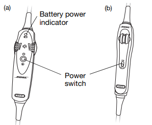
If you experience loud tones and the related loss of communication, turn off the power switch. The headset will continue to provide communications in the passive noise-reducing mode. ANR mode is active when the headset control module power switch is set to ON (Figure 1) or when the battery power indicator is lit. The headset is in the passive mode when the power switch is set to OFF, or when the battery power indicator is unlit.
Power source
Your headset is one of two types: battery-powered, or aircraft powered. If your headset is battery-powered, make sure it is connected only to battery power. If your headset is aircraft powered, connect the headset to the aircraft power sources only as described in this guide. An aircraft-powered headset will not operate properly if used with a Bose Series II Aviation Headset battery pack or with any commercial battery pack.
Description
The Bose Aviation Headset uses a vanned combination of elective-acous1ical noise reduction circuitry and a pa1en1ed cushioning system 10 significantly reduce aircraft noise. The Bose Headset actively reduces noise elements in addition to 10 muffling noises. The patented ClearComfon· cush passive noise attenuation. As a result, this Headset can be worn comfortably for extended periods. F0< proper operation. a Bose Aviation Headset must be connected 10a Bose Headset interface. The Interface pov,-ers the Headset’s active noise-reducing electronics and matches the Headset to the aircraft’s avionics.
We appreciate your choice
Congratulations on your purchase of a Bose® Aviation Headset. This headset combines Bose Acoustic Noise Cancelling® headset technology to electronically reduce unwanted aircraft noise, and Bose TriPort® headset technology for a smaller, lighter, more comfortable headset that delivers full-spectrum noise reduction. We believe it is the finest aviation headset you can own.
Headset and cable variations
The Bose Aviation Headset is available in variations designed for general aviation and helicopter use. There are also battery-powered and aircraft-powered versions. The communications cable for your headset may be either straight or coiled, depending on the headset configuration you have purchased.
Features common to most variations:
- Acoustic Noise Cancelling headset technology
- TriPort headset technology
- Communications cable with an integrated control module
- Flexible microphone boom with continuous position adjustments
- Adjustable headband
- Replaceable ear cushions
- Replaceable fleece headband cushion
- Replaceable windscreen
- Cable-mounted clothing clip

Locate the serial number for your product registration card
The Bose® Aviation Headset includes a product registration card in the carton. Please fill in the requested information and mail it to Bose. We will use this information to provide you with appropriate advisories and updates. Be sure to include your headset serial number, which can be found on the barcode label located on the underside of the magnesium headband, underneath the headband cushion.

After locating your headset serial number, be sure to properly replace the headband cushion by pressing down firmly. For more information on replacing the headband cushion.
Date of manufacture
Your headset’s date of manufacture is an important part of your serial number. It is the underlined, four-digit number that begins just after the first alphabetic letter in the serial number. Example: 031963E31920040E In this example, the date of manufacture is 3192. The first digit, 3, refers to the year of manufacture (2003). The last three digits, 192, refer to the day of the year (the 192nd day of 2003).
Decide where you want the boom microphone
Depending on the headset configuration you purchased, your headset may arrive with the boom microphone cable attached to the left earcup or packed separately in the carton. In either case, you can attach the boom microphone cable to either earcup, as preferred. Before you remove or attach the microphone, however, be sure to note the important markings for left (L) and right (R) above each earcup. These markings indicate which ear each earcup is intended to fit over.
Removing an attached boom microphone cable
- Use a Phillips or straight-blade screwdriver to loosen the two screws at the base of the boom microphone cable assembly.
- Pull the cable assembly straight out from the earcup to which it is attached.
CAUTION: Do not twist the boom microphone cable while disconnecting it. Twisting can damage the connector pins.

Attaching the boom microphone cable
Before you attach the boom microphone, make sure that the cable connector and its earcup connector are clean and free of debris.
- Use a Phillips or straight-blade screwdriver to loosen the two screws on the access cover near the bottom of the earcup where you want to attach the boom microphone.
- Remove the cover to reveal the connector pins on the earcup.
- Carefully line up the connector to the small connector pins on the panel

- Press the assembly onto the connector pins until it is fully engaged and the cable assembly is flush with the earcup.
CAUTION: Do not apply excessive force, which may result in earcup damage. - With the screw threads properly aligned, tighten the screws.
- Rotate the microphone boom into position so it will be near your mouth when you put on the headset. The label should be facing your lips.
- Attach the access cover to the connector panel on the earcup that does not have the boom mic attached. Align the screws and tighten them to secure the cover.

Preparing to use battery power
The battery compartment on your headset control model serves two purposes. In addition to holding the batteries, it contains small switches (Figure 9) that give you the option to change some of the factory-set operation defaults for your headset.

Changing the optional operation switches
Note: To change switch positions, use a pen or a small, flat-tipped screwdriver to gently switch the tab.
- Switches 1- 3: Not currently used.
- Switch 4: Set at the factory to enable the smart shutoff function. To disable smart shutoff, set the switch to OFF. With the switch in the OFF position, the ANR system will not turn off until the power button is depressed and held for at least one second.
Inserting batteries
Insert the two supplied alkaline AA batteries (IEC LR6) into the control module.

CAUTION:
The battery compartment is designed to prevent inadvertent reverse polarity from installing the batteries incorrectly. If the batteries do not seem to fit correctly, do not force them in. Forcing an improper connection will cause permanent damage to the control module
For proper Headset fit
NOTE;
The Headset should bew0<n with the sloped surtaxes and the ear cups facing forward. Follow these suggestions 10 to achieve maximum comfort and perf0<mance. Adjust both sides of the headband equally 10 provides a balanced force on your head. To achieve a good seal. lightly grasp both ear cups and POsition them so Iha! Your ears are completely inside the Clear C0<nfort· cushions.
If you experience either a hiss or a low rumbling sound, this may indicate,e an improper fit Extending the headband slightly should correct eel this condition. Wearing hats° glasses with! hick temples may meter and cause a problem. Final adjustment is best accomplished in a noisy environment with the Headset system turned on. Then. reposition both ear cups until the Headset seems quietest.
Care and Maintenance
Stowing the Headset
Bose recommends that you do not leave! the Headset in your cockpit or in direct sunlight between flights. for several reasons. While! the Headset has been designed for storage at temperatures up to 1SS°F (70•C). cumulative exposure to 10 high temperatures will slowly cause changes in the electret microphone elements in the earcups, reducing their active noise reduction performance. Additionally. the gel in the Clear Camion· Cushion stores heat. Wearing the Headset after it has remained in an extremely hot or cold cockpit may be uncomfortable for several minutes. To assure many years of enjoyment and to protect your investment. take your Headset with you when you leave the aircraft. A lined, drawstring bag has been provided with the system, for Slowing the Headset between nights. To slow the Headset:
- Bendandro1atelheboomintheclipso that ! he boom extends below and ! hen up the side of the opposite earcup
- Coiflhe Headset cab? e; do not wrap 1he cable around the yoke arms. This avoids pulling the cushions together and compressing 1hem.
- Place the Headset in its storage position with the earcups resting cushion-10- cushion in the drawstring bag.
NOTE: If you place the Portable Interface in the bag as well, be careful not to scratch 1he finish on the Headset.
Preparing the aircraft powered headset for use
For permanent installation of the headset, the harness (material number 323172-0010) is installed into the aircraft. The 3-foot wiring harness includes a self-latching, precision designed, quick connector for panel mounting in the aircraft. The connector is mechanically keyed to ensure proper mating. To order additional harnesses, call Bose at 1-800-242-9008.
Note:
The aircraft panel connector must be mounted and documented by qualified personnel to perform this type of avionics installation into the aircraft being used. Consult your local FAA office or aviation authorities to determine the appropriate documentation required. The Bose connector (material number 323172-0010) is TSO approved (C-57a and C-58a) together with the Bose Series II Aviation Headset and the Bose Aviation Headset X.
Attaching and removing the cable
When the quick-connector is installed, the cable leading from the control module connects to it. Match the narrow bar on the cable end to the slot on the connector. Press in until the two parts engage. To release the cable, pull back on the sleeve near the end of the cable. Then gently remove the cable from the connector.
CAUTION:
Do not attempt to pull the connector out without first pulling back on the sleeve. Forcing the connector out will cause damage to the cable and/or your aircraft instrument panel.

Mounting the connector
Mount the connector into a cutout. Connect the eight wires as follows:
- Two for the microphone
- Two for audio
- One for power
- One for ground
- Two for audio shields
Audio and microphone wires should be connected to the back of the existing microphone and headphone jacks, leaving existing jacks intact for use with conventional headsets. This is usually the fastest installation method (see Figures 1 – 4 for reference). Audio shields should be connected to ground at the existing jack. (Caution: Use of two headsets wired in parallel is not advised. This may result in reduced performance.)

Cleaning instructions
Clean the Headset exterior and cushions by wiping them with a moist cloth. Mild soap may be used if necessary. Do not immerse the Headset in water. The headband cover may be, removed and washed by hand in mild soap and cool water if it becomes soiled. To remove it. extend the headband to maximum height. unsnap the cover at each end. and peel the Velcro apart along the top flap. After washing, allow the cover to air dry before placing it on the headband. Replace the headband covet with the opening to the ear.
Clear Comfort· cushion
To order a replacement cushion kit, call the Bose Aviation Headset Order Department. 1·800-242-9008. Bel0te 0tdering, remove the cushions and inspect the earcup foam liner. If you note significant deteri0tation in the line<s, please order < a line, replacement also.
To remove the cushion and liner
- Place the Headset with the yoke arms crossed. so that the cushions are facing outwards o, both sides
- Unsnap the black trim ring on one ear cup by prying 1he middle rear with the edge of your finger. Do not use a hard object such as a screwdriver, which can mar the earcup. Once 1he trim ring has popped free in the back. v.’Otk your way around the ear cups until the trim ring is completely free.
- Lift the Old cushion off. If you will be installing a new line<. proceed to the next section, Otherwise, skip to “To replace the cushion”


To clean the cushion
Use a baby wipe or a cloth moistened with isopropyl alcohol, gent1′,’ and wipe the side of the cushion Iha! touches the ear. Let 111e cushion air dry. then dust with talcum powder.
To replace the cushion
- Place the new cushion inside the trim ring. Align the cushion/l!im ring. will its flat edge forward, to the ear cup.
NOTE: The small holes in each of the cushions should nest on the posts on the ear cup. If both old cushions have been removed, note that there are left and rig hi trim rings. The left ring will not fit on the right earcup. - Snap the trim ring down firmly along its circumference. Make sure that the trim ring is no1 grabbing the side of the cushion at any spot If it is, pull the sl<in of the cushion free at Iha! spot
- Replace the foam liner and cushion on the other ear cup! in the same manner.
Microphone boom relocation
To suit your personal preference, the Headset boom can be moved from one ear cup to the other. This requires the use of a small screw driver and can be accomplished as follows:
- Remove the headband cover by extend• ing the headband to maximum height. Unsnap each end of the headband cover and peel apan the Velcro seam.
- Remove the boom from the clip by pulling the boom down just in front of the clip 10 snapshots.
- Use a small screwdriver to remove the screw holding the clip. The screw is held captive by an E-ring, which must be in place f0< the assembly to WOii< directly.
- Using the same screw. fasten the clip to the other earcup. Be sure the E-ring is in place and seated. The angled face of the clip should be positioned toward the rear. Tighten the screw until it bottoms. Oo does not continue to tighten. Friction in turning this way ensures that the screw does not lose over time.
- Unwind the boom and cable from the ear cup cable. Remove the boom cable from the groove at the rear of the pivot block.
Reference Link
https://www.bose.com/en_us/products/headphones/aviation_headsets.html


