
DEFIANT 49814 Daylight Adjusting Indoor Digital Timer Manual

Before You Begin:
Product Features
- Set one or more multiple ON/OFF settings for each day of the week, daily cycles, or weekday – weekend cycles
- Stores up to 7 individual programs
- A Random feature that turns the lights off and on between 30 minutes before and after the programmed time, giving the appearance that somebody is currently home.
Pre-Installation Requirements
- This timer requires that your switch box have a neutral wire in order for the timer to operate correctly. If you open up your switch box and only see 2 wires, this indicates that your switch box does not have a neutral wire and this timer will not work.
- This timer will work in a single pole or 3-way installation. It will not work in a 4-way installation.
- This timer will only work on loads up to 15 amps.
CHANGING THE FACEPLATE
This device includes a light-almond faceplate. To switch faceplates, follow the steps below.
- a. Gently remove the white faceplate using a flathead screwdriver. Starting at the top left corner, gently pry the faceplate loose, working around the edge until it pops off.
- b. Find the light-almond faceplate in the package. Place the new faceplate into position and carefully push until it snaps into place.
Product Specifications
- Single pole or 3-way installation

Hardware Included

Suggested Tools

REMOVING SIDE SECTIONS FOR MULTI-SWITCH INSTALLATIONS
When installing your timer into a wall box with multiple switches, remove all the inner side sections prior to making the electrical connections. See Figure 1.
- a. Use pliers to bend the side section up and down until it breaks off.
- b. Repeat the process for each side section to be removed.

Installation Terms and Options
BASIC WIRING TERMINOLOGY
To better familiarize yourself with the wiring terminology and concepts referenced in this manual, please review the following information before you begin wiring this timer to your switch outlet. If at any time during the wiring process, you become uncertain, please contact a certifi ed electrician.
- Line: This is the 120 AC (hot) from breaker box.
- Load: This is the 120V AC wire that controls the fi xture (load out) which carries power to the light.
- Neutral: 120-volt return connection.
- Ground: 120 safety ground.
- Traveler-1 and Traveler-2: Wires running between two 3-way switches for installations where a light is controlled by two switches.
INSTALLATION OPTIONS
To begin the installation process, you must first know what type of installation is needed. Below are the 3 different installation options. Please refer to the following descriptions for the installation instructions that apply to you.
- Single-Pole Installation (Go to install section 1 on page 2): This installation option should be used when a switch only controls one outlet from a single location. A typical example of where you would find a single-pole switch is your bedroom or bathroom light switch.
- 3-Way Installation, Load Side (Go to install section 2 on page 2): This installation option replaces a switch that controls a light that can be controlled from two locations and in most installations has the common (hot) terminal tied to the lamp/load the switch turns OFF and ON. Typically these types of installations are in stairwells, hallways, and large rooms with multiple access points.
- 3-Way Installation, Line Side (Go to install section 3 on page 2): This installation option replaces a switch that controls a light that can be controlled from two locations and in most installations has the common (hot) terminal tied to 120VAC. Typically these types of installations are in stairwells, hallways, and large rooms with multiple access points.
Single Pole Installation
Disconnect the power at the circuit breaker or fuse box
- a. Remove the existing switch.
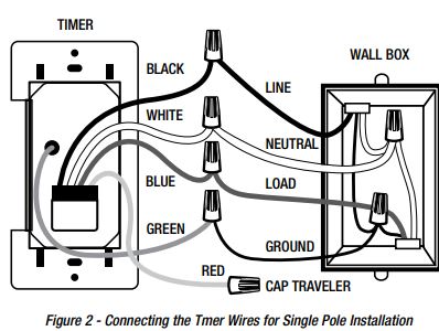
- b. Connect the wires of the timer to the wall box as shown, using the wire nuts provided. See Figure 2.
- Connect the hot/live wire of the line to the black wire from the timer.
- Connect the hot/live wire of the load to the blue wire from the timer.
- Connect the ground wire to the green wire from the timer.
- Connect the neutral wire to the white wire from the timer. Often the neutral (white) wire can be found in the back of the wire box
- connected with a wire nut. There may be several neutral wires bound together. Add the timer neutral to all neutral wires bound
together making sure the wire nut is tight.- Attach a wire nut to the red (traveler) wire from the back of the timer. This wire is not needed in the single pole installation.
- c. Ensure that all wire nuts are secure, and tuck the wires into the wall box, leaving room for the timer.
- d. Use the screws (CC) to mount the timer to the wall box, being careful not to crush any wires.
- e. Reinstall your wall plate.
- f. Turn the main power ON at the circuit breaker.
- g. If the timer display does not turn on, disconnect the power at the circuit breaker or fuse box. Swap the black and blue wires on the timer. Remount the timer and wall plate, then restore power at the fuse box or circuit breaker.
Load Side 3-Way Installation Instruction
PREPARING THE SWITCH ON THE LINE SIDE
- a. Disconnect the power from the circuit by turning off the circuit breaker or removing the fuse from the fuse box.
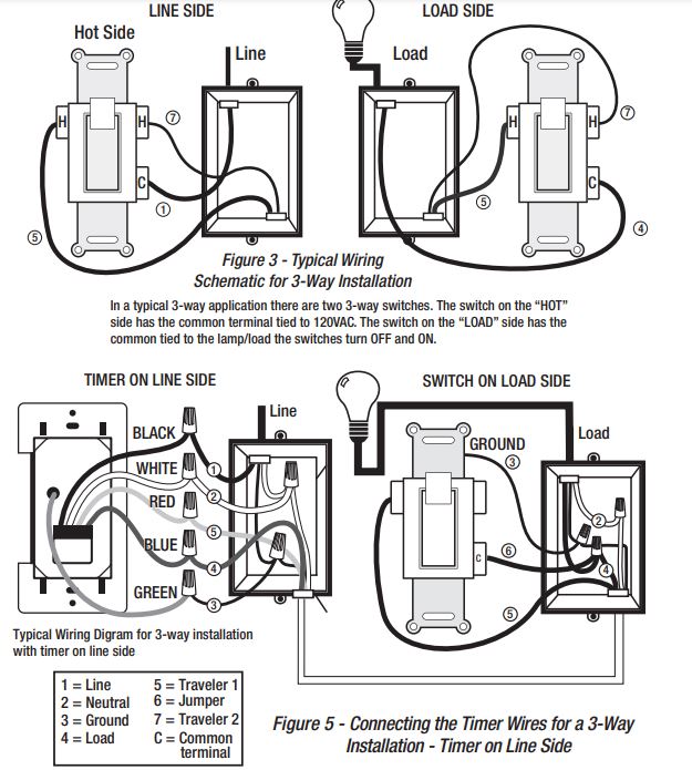
- b. Using the Line Side of Figure 3 shown below as a reference, label and remove the line wire (1) from the common terminal and the Traveler-2 wire (7).
- c. Connect the jumper wire (supplied part DD), the line wire (1) from the common terminal C, and the Traveler-2 wire (7) together. You should have three wires connected with one wire nut.
- d. Connect the other end of jumper (6) back to the common terminal (C) on the switch. Consider recording the marking/color coding of the Traveler-1 (5) and Traveler-2 (7) wires so you can tell them apart for later use.
- e. Tuck the wires into the box, leaving room for the switch.
- f. Install the switch back into the box.
INSTALLING THE TIMER ON THE LOAD SIDE
- a. Using Figure 3-Load side as a visual guide, remove the load side 3-way switch and the three wires, labeling the wire on the common terminal as Load (4) and the traveler wires.
- b. Connect the removed LOAD wire (4) to he blue wire of the timer.
- c. Using Figure 4 -Timer on the Load Side as a visual reference for the remaining steps, connect the Traveler-1 wire (5) to the black (line) wire from the timer.
- d. Connect the Traveler-2 (7) wire to the red traveler wire from the timer.
- e. Connect the white wire from the timer to the white neutral wire (2) from the switch box. The neutral wires may be bundled in the back of the switch box with a wire nut, and there may be several neutral wires bound together. Add the neutral to all neutral wires bound together, making sure the wire nut is tight.
- f. Connect the green wire from the timer to the ground wire (3) in the switch box. g. Tuck the wires into the switch box, leaving room for the timer.
- h. Use the supplied screws to install the timer, being careful not to crush or pinch the wires.
- i. Restore power at the circuit breaker or fuse box.
- j. If the light fi xture does not operate properly, disconnect the power at the circuit breaker or fuse box. Then swap the line wire (1) and traveler wire (5) on the timer.
- k. Verify that the light fi xture turns ON and OFF when you manually turn the timer ON and OFF. Perform this test with the remote switch in both positions. You should hear the timer relay click ON/OFF. If you hear the relay click but the light fi xture does not turn ON/OFF properly, check your wiring.

Line Side 3-Way Installation Instruction
PREPARING THE SWITCH ON THE LOAD SIDE
- a. Disconnect the power from the circuit by turning off the circuit breaker or removing the fuse from the fuse box.
- b. Using the Switch on the Load Side of Figure 3 shown below as a reference, label and remove the load wire (4) from the common terminal and the Traveler-2 wire (7).
- c. Using Figure 5 as a visual reference, connect the jumper wire (6 (supplied part DD)), the load wire (4) from the common terminal (C), and the Traveler-2 wire (7). You should have three wires
- connected with one wire nut.
- d. Connect the other end of the jumper (6) back to the common terminal (C) on the switch. Consider recording the marking/color coding of the Traveler-1 (5) and Traveler-2 (7) wires so you can tell them apart for later use.
- e. Carefully tuck the wires into the switch box leaving room for the timer.
- f. Install the switch back into the box.
INSTALLING THE TIMER ON THE LINE SIDE
- a. Using Figure 3 shown above – Line Side, as a visual guide, remove the line side 3-way switch and wires, and label the wire removed from the common terminal (C).
- b. Using Figure 5 below – Timer on Line Side as a visual guide, connect the line wire (1) to the black wire from the timer using the supplied wire nuts.
- c. Connect the white wire from the timer to the neutral wire (2) (white). The neutral wires may be bundled together in the back of the box, and there may be several neutral wires bound together. Add the neutral to all neutral wires bound together, ensuring the wire nut is tight.
- d. Connect the traveler-1 wire (5) to the red wire from the timer and the load wire (4) to the blue wire from the timer. Connect the green wire to the ground wire (3) (green or bare wire in box).
- e. Carefully tuck the wires into the switch box, leaving room for the timer.
- f. Use the supplied screws to install the timer, being careful not to crush or pinch the wires.
- g. Restore power at the circuit breaker or fuse box.
- h. Verify that the load turns ON and OFF when you manually turn the timer ON and OFF. Perform this test with the remote switch in both positions.
- i. If the load does not operate properly, disconnect the power at the circuit breaker or fuse box. Then swap the load wire (4) and traveler wire (5). This can be done at the timer or the toggle switch
Initial Setup
PRODUCT DESCRIPTION

| Part | Description |
| A | ON/OFF: Timer override (push to turn on or off) |
| B | SETUP: Press once to set the calendar/clock. Press twice to set or change programming. |
| C | + and –: Press to scroll through menu options. |
| D | RESET: Press and hold for three seconds to reset the timer. |
| E | AUTO: Press once to activate the timer after programming is complete. Press once to return to Auto mode when in Manual mode or Random mode. |
| F | RND: Press once to activate the random feature. |
| G | ENTER: Press to confirm indicated settings. |
| H | TIMER DOOR: Close after programming. Press to turn ON/OFF (timer override). |
Product Features
- Set one or more multiple ON/OFF settings for each day of the week, daily cycles, or weekday – weekend cycles
- Stores up to 7 individual programs
- A Random feature which turns the lights off and on between 30 minutes before and after the programmed time, giving the appearance that somebody is currently home.
SETTING THE TIMER UP FOR THE FIRST TIME

- a. Remove the protective fi lm from the screen.
- b. Using the tip of a pencil, gently press and hold RESET until you see the word “RESET” scroll across the screen. See Figure 6. Release the button and “12:00 AM” will begin to fl ash.
- c. Press SETUP and “CAL” will begin to fl ash (See Figure 7). Press ENTER to begin setting the calendar, and the year will begin to fl ash.
- d. Press + or – to set the current year. Press ENTER, and the month will begin to fl ash. See Figure 8.
- e. Repeat the sequence in step d. to set the current month, day, hour, and minute. When DST appears on the display (see Figure 9), continue to step f to set the Daylight Savings Time (DST) setting.
- Press the + or – button (C) to turn Daylight Savings time ON/OFF. Press ENTER to confi rm.
- g. If you selected DST ON, the display fl ashes “ZONE”. Proceed to step 2 – SETTING THE DAWN/DUSK REGION (ZONE).
SETTING THE DAWN/DUSK REGION (ZONE)
View Figure 10 and determine which zone best fi ts your location. The options are NOR: North, CENT: Central, SOUT: South, HAWA: Hawaii, and ALAS: Alaska.

- a. “ZONE” will be fl ashing on your screen. Press ENTER to begin setting your region, and “NOR” will begin to fl ash. See Figure 11. Use + or – to select the zone identifi ed. Press ENTER to confi rm, and “DAWN” will be displayed with an approximate dawn time for your area. See Figure 12A. This is pre-programmed DAWN time for your area. If this time is acceptable for you, press ENTER and proceed to step d. If you would like to change this time, proceed to step b.
- b. Press + or – to set your current dawn hour. Press ENTER to confi rm.
- c. Press + or – to set your current dawn minute. Press ENTER to confi rm, and “DUSK” will be displayed.
- d. Use the same process to set the dusk hour and minute, and “SAVE” will be displayed. See fi gure 12B.
- e. Press ENTER to save the current date and time information.
Programming
PROGRAMMING THE ON/OFF DAYS

- a. Press SETUP twice to begin programming ON/OFF days, and “P1 ON” will display.
- b. Press ENTER once, and “SET” will display. Press ENTER again to begin setting the ON time, and “PRG” will be displayed with the days of the week fl ashing. See Figure 13.
- c. Press + or – to select the day(s) you want this program to turn the timer ON:
- S, S (Saturday and Sunday)
- M, T, W, Th, F (weekdays only)
- S, M, T, W, Th, F, S (individual days)
- T, Th (Tuesday and Thursday)
- M, W, F (Monday, Wednesday, and Friday)
- S, M, T, W, Th, F, S (default: all days of the week)
- d. Press ENTER to confi rm the setting. Proceed to the next step – PROGRAMMING THE ON/OFF TIME.
PROGRAMMING THE ON/OFF TIME

- a. Press + and – to choose from one of these three options to begin confi guring the timer’s ON time. Proceed to step b when you are fi nished setting one of these three options:
- DAWN: This is the default screen. When you reach this screen, press ENTER to set the timer’s ON time to the DAWN time that is displayed. See Figure 14.
- DUSK: When you reach this screen, press ENTER to set the timer’s ON time to the DUSK time that is displayed. See Figure 15.
- TIME: When you reach this screen, press ENTER (see Figure 16). When the hour begins to fl ash, press + or – to scroll to the desired hour, paying attention to the AM/PM setting in the corner of the display. Press ENTER when the hour is correct. The minute will begin to fl ash on the screen. Press + or -, followed by ENTER to set the minute.
- b. When “P1 OFF” and “PRG” display, follow steps 1c through 2a to set the OFF days and times.
- c. Once fi nished, “SAVE” will appear. See Figure 17. Press ENTER to save this program, and “P2 ON” will be displayed, with P2 fl ashing. If you need additional programs, press ENTER and repeat steps 1c through 2b to set the next program ON/OFF times. When you are fi nished programming ON/OFF times, press AUTO to complete the programming.
Additional Programming Options
DELETING PROGRAMS

- a. Press SETUP twice, followed by + or – to scroll to the program you wish to delete. Press ENTER and “SET” will display.
- b. Press + or – until the display shows “DEL,” then press ENTER. See Figure 18.
- c. The program is now deleted, and you may press + or – to select another program for deletion following the steps above. Press AUTO when you have completed deleting all desired programs.
SETTING THE RANDOM (RND) SECURITY OPTION
The random feature will turn the lights ON and OFF using the programmed times “+” or “-” 30 minutes, giving the house a more lived-in appearance while the occupant is away.

- a. Push RND to activate the random feature. The screen will change from “AUTO” to “RDM”. See Figure 19.
- b. Push AUTO to de-activate the random feature and return the timer to its current programming.
Additional Features
USING THE MANUAL OVERRIDE FEATURE (OPTIONAL)
To manually override the timer and turn the lights off and on at your convenience, there are two options:
- Manual override with active programming: Press the timer door or the ON/OFF button, which will turn the lights on and off. In this option, your programs will still be active and the override will only last until the next scheduled program.
- Manual override with inactive programming: Following these steps will inactivate the programing. In this setting, you must press the ON/OFF button or the timer door for the lights to turn on and off.
- a. Press and hold + and – at the same time until you see “MAN” display on the screen.
- b. Now your timer will work like a manual switch, just press on the timer door or the ON/OFF button to turn the lights on and off at your convenience.
- c. To return your timer to AUTO mode (where your programs are activated), press and hold + and – at the same time and the timer will go back into AUTO mode.
COUNTDOWN MODE
- Press and hold the On/Off button for about 2 seconds.
- Display will show 10, 20, 30, 40, 50 min., 1 HR, 1.5 HR, 2 HR, 3 HR.
- Release button when desired countdown time is displayed.
- Timer will stay on for this time and then return to previous mode.
FCC NOTE
This device complies with part 15 of the FCC and Industry Canada license-exempt RSS standard(s). Operation is subject to the following two conditions: (1) this device may not cause harmful interference, and (2) this device must accept any interference received, including interference that may cause undesired operation.
FCC NOTE:
The manufacturer is not responsible for any radio or TV interference caused by unauthorized modifications to this equipment. Such modifications could void the user’s authority to operate the equipment. NOTE: This equipment has been tested and found to comply with the limits for a Class B digital device, pursuant to Part 15 of the FCC Rules. These limits are designed to provide reasonable protection against harmful interference in a residential installation.
This equipment generates, uses, and can radiate radio frequency energy and, if not installed and used in accordance with the instructions may cause harmful interference to radio communications. However, there is no guarantee that interference will not occur in a particular installation. If this equipment does cause harmful interference to radio or television reception, which can be determined by turning the equipment off and on, the user is encouraged to try to correct the interference by one or more of the following measures:
- Reorient or relocate the receiving antenna.
- Increase the separation between the equipment and the receiver.
- Connect the equipment to an outlet on a circuit different from that to which the receiver is connected.
Consult the dealer or an experienced radio/TV technician for help CAN ICES-3(B)/NMB-3(B)