Emerson Sensi Wi-Fi Heating & Air Conditioning

PREPARATIONS
Assemble tools required as shown below.
 Failure to follow and read all instructions carefully before installing or operating this control could cause personal injury and/or property damage.
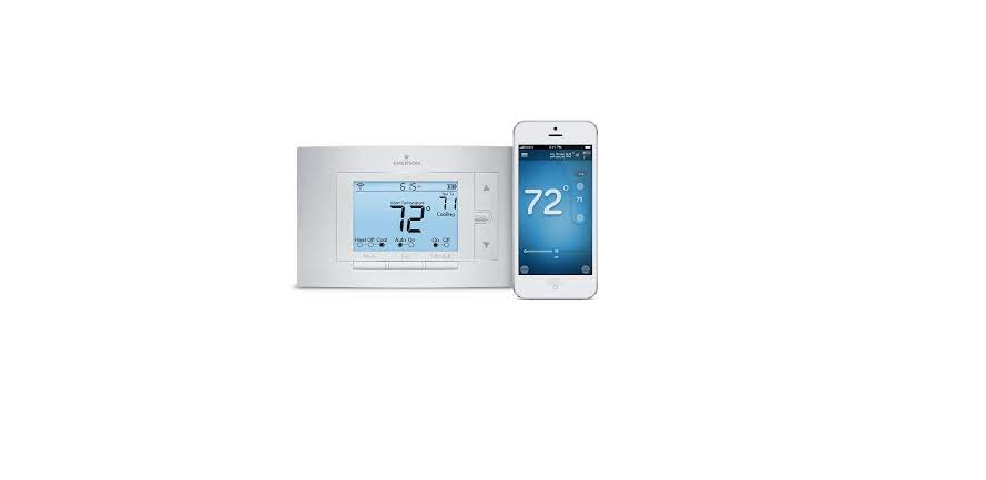
THERMOSTAT DETAILS

- W904 – clip for Celcius display
- W905 – clip for hydronic system
NOTE: Earlier models refer to 37-7006 for jumper locations.
REMOVING OLD THERMOSTAT
CAUTION
To prevent electrical shock and/or equipment damage, disconnect electric power to the system at the main fuse or circuit breaker box until installation is complete. Before removing wires from the old thermostat’s switching subbase, label each wire with the terminal designation it was removed from.
- Remove Old Thermostat: A standard heat/cool thermostat consists of three basic parts:
- . The cover may be either a snap-on or hinge type.
- The base is removed by loosening all captive screws.
- The switching subbase is removed by unscrewing the mounting screws that hold it on the wall or adaptor plate.
- Shut off electricity at the main fuse box until installation is complete. Ensure that the electrical power is disconnected.
- Remove the front cover of the old thermostat. With wires still attached, remove the wall plate from the wall. If the old thermostat has a wall mounting plate, remove the thermostat and the wall mounting plate as an assembly.
- Identify each wire attached to the old thermostat using the labels enclosed with the new thermostat.
- Disconnect the wires from the old thermostat one at a time. DO NOT LET WIRES FALL BACK INTO THE WALL.
- Install a new thermostat using the following procedures.
REMOVING OLD THERMOSTAT
ATTENTION!
This product does not contain mercury. However, this product may replace a unit that contains mercury. Do not open mercury cells. If a cell becomes damaged, do not touch any spilled mercury. Wearing non-absorbent gloves, take up the spilled mercury and place it into a container that can be sealed. If a cell becomes damaged, the unit should be discarded. Mercury must not be discarded in household trash. When the unit this product is replacing is to be discarded, place it in a suitable container. Refer to www.whiterodgers.com for locations to send products containing mercury.
MOUNTING AND WIRING
WARNING
Do not use on circuits exceeding specified voltage. Higher voltage will damage control and could cause shock or fire hazards. Do not short out terminals on the gas valve or primary control to test. Short or incorrect wiring will damage the thermostat and could cause personal injury and/or property damage. Thermostat installation and all components of the system shall conform to Class II circuits per the NEC code.
Hydronic (Hot Water or Steam) Heating Systems
This thermostat is set to operate properly with a forced-air heating system. If you have a hydronic heating system (a system that heats with hot water or steam), you must set the thermostat to operate properly with your system. The factory default setting is forced air heat. Clipping jumper W905 on the circuit board will produce a longer heating cycle which is normal for hot water or steam (hydronic) systems. Both settings produce a very accurate temperature control and can be set to your personal preference. As received, the thermostat cycles the system just under 1°F. With W905 clipped, the system cycles at approximately 1.5°F.
CAUTION
Take care when securing and routing wires so they do not short to adjacent terminals or the rear of the thermostat. Personal injury and/or property damage may occur.
Attach Thermostat Base to Wall
- Remove the packing material from the thermostat. Gently pull the body straight off the base. Forcing or prying on the thermostat will cause damage to the unit.
- Connect wires beneath terminal screws on the base using the appropriate wiring schematic.
- Place the base over the hole in the wall and mark the mounting hole locations on the wall using the base as a template.
- Move the base out of the way. Drill mounting holes.
- Fasten the base loosely to the wall, as shown in fig. 1, using two mounting screws. Adjust until level, and then tighten screws. (Leveling is for appearance only and will not affect thermostat operation.) If you are using existing mounting holes, or if the holes drilled are too large and do not allow you to tighten the base snugly, use plastic screw anchors to secure sub base.
- Push excess wire into the wall and plug the hole with a fire-resistant material (such as fiberglass insulation) to prevent drafts from affecting thermostat operation.
Battery
Location This thermostat requires 2 “AAA” alkaline batteries to operate. If appears on the display, the batteries are low and should be replaced with fresh premium brands “AAA” alkaline batteries such as Duracell® or Energizer®. The batteries are located on the back of the thermostat body.
CHECK THERMOSTAT OPERATION
NOTE
To prevent static discharge problems, touch the side of the thermostat to release static build-up before touching any keys. If at any time during testing your system does not operate properly, contact a qualified service person.
Heating System
- Move the SYSTEM switch to the HEAT position. If the heating system has a standing pilot, be sure to light it.
- Press to adjust the thermostat setting above room temperature. The heating system should begin to operate.
- Press to adjust the temperature setting below room temperature. The heating system should stop operating.
Before you begin using your thermostat, you should be familiar with its features and with the display, and the location and operation of the thermostat buttons. Your thermostat consists of two parts: the thermostat body and the base. To remove the body, gently pull it straight out from the base. To replace the body, line up the body with the base and press gently until the body snaps onto the base.
The Thermostat Buttons and Switches
- (Up arrow) Raises temperature setting.
- (Down arrow) Lowers temperature setting.
- SYSTEM switch (OFF, HEAT)
Operating Features
Now that you are familiar with the thermostat buttons and display, read the following information to learn about the many features of the thermostat.
- TEMPERATURE SETTING — Press until the display shows the temperature you want. The thermostat will keep the room temperature at the selected temperature.
- °F/°C CONVERTIBILITY — The factory default setting is Fahrenheit. Clipping the W904 jumper on the circuit board (see fig. 1) will alter this feature to the Celsius temperature setting.

- LOW BATTERY INDICATOR — If the 2 “AAA” alkaline batteries are low and should be replaced, the display will be blank except for. When the batteries are low, pressing any button will cause the display to operate for ten seconds. After ten seconds, the display will be blank except for. After has been displayed for 4 weeks, the thermostat will drop the temperature 10° below your setpoint in HEAT mode. You cannot program with low batteries but you can override the setpoint temperature.
- TEMPERATURE DISPLAY ADJUSTMENT — Your new thermostat has been accurately set up in our factory. However, if you wish, you may adjust your new thermostat temperature display to match your old thermostat. This can be accomplished (within a ±3° range) as follows:
- Press and at the same time for two seconds with the SYSTEM switch in the OFF position.
- Press or adjust the displayed temperature to your desired setting.
- Move the SYSTEM switch from OFF to exit the feature
- DISPLAY BACKLIGHT— The display backlight improves display contrast in low-lighting conditions. Selecting the backlight ON will turn the light on for a short period of time after any button is pressed. Selecting the backlight OFF (default) will keep the light off. Turn the display backlight feature ON as follows:
- Press and at the same time for two seconds with the SYSTEM switch in the HEAT position. The display will alternately show “-L” AND “FF” (off).
- Press or change “FF” to “ON”.
- Move the SYSTEM switch to OFF to exit the feature.
Reference Link
https://sensi.emerson.com/en-us/products/wifi-thermostat
PDF Link
https://climate.emerson.com/documents/1e78-140-installation-instruction-en-us-4209046.pdf

