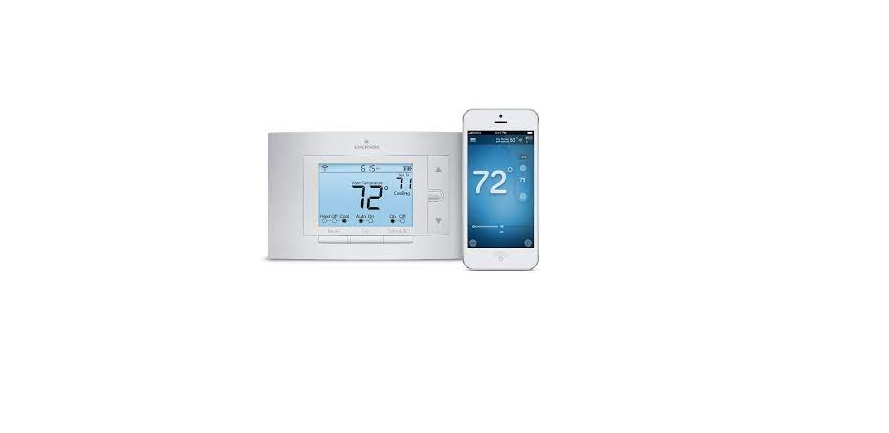
Emerson Sensi Wi-Fi Instructions

Your new White-Rodgers 5-Day/1-Day/1-Day Digital Thermostat uses the technology of a solid-state microcomputer to provide precise time/temperature control. This thermostat offers you the flexibility to design heating and cooling programs that fit your needs.
Features
- Separate 5-day (weekday), 1-day (Sat), and 1-day (Sun) programming with four separate time/temperature periods per day
- Simultaneous heat and cool program storage
- Preprogrammed temperature control
- Backlit display
- LCD continuously displays setpoint and alternately displays time and room temperature.
- Temperature override until the next program period
- Manual program override (HOLD temperature)
- Temporary HOLD
- °F/°C convertibility
- Temperature range from 45° to 90°F
- RC, RH, C, W, Y, G, O, and B terminals
- Optional C terminal (Dual Power option)
- B and O terminals for single-stage heat pumps (no auxiliary heat) or damper operation
- Program storage in case of power loss
- 2 “AA” alkaline batteries are included.
This thermostat is intended for use with a low-voltage system; do not use this thermostat with a line-voltage system. If in doubt about whether your wiring is millivolt, line, or low voltage, have it inspected by a qualified heating and air conditioning contractor or electrician. Do not exceed the specification ratings. All wiring must conform to local and national electrical codes and ordinances. This control is a precision instrument and should be handled carefully. Rough handling or distorting components could cause the control to malfunction.
CAUTION
To prevent electrical shock and/or equipment damage, To prevent electrical shock and/or equipment damage, To prevent electrical shock and/or equipment damage, To prevent electrical shock and/or equipment damage, disconnect electric power to the system at the main fuse or circuit breaker box until installation is complete.
WARNING
Do not use on circuits exceeding specified voltage. Do not use on circuits exceeding specified voltage. Higher voltage will damage control and could cause shock or fire hazards. shock or fire hazard. shock or fire hazard. shock or fire hazard. Do not short out terminals on gas valve or primary control Do not short out terminals on the gas valve or primary control Do not short out terminals on gas valve or primary control Do not short out terminals on gas valve or primary control to test. Short or incorrect wiring will damage the thermostat to test. Short or incorrect wiring will damage the thermostat and could cause personal injury and/or property damage. age. Thermostat installation and all components of the system shall conform to Class II circuits per the NEC code.
APPLICATIONS
For use with
- Standard heat/cool or heat-only systems
- Electric heat systems
- Gas or oil-fired systems
- Gas systems with intermittent ignition devices (I.I.D.) and/or vent dampers
- Hydronic (hot water or steam) systems
- Single-stage heat pump systems (no auxiliary heat)
- Millivolt systems
DO NOT USE WITH:
- Multi-stage systems
- • Systems exceeding 30 VAC and 1.5 amps
- 3-wire zoned hydronic heating systems

Typical diagram for heat-only, 3-wire, single transformer systems.

Typical wiring diagram for heat/cool, 5-wire, two-transformer systems/

wiring Typical diagram for cool-only, 3-wire, single transformer systems.

wiring diagram for heat pump with reversing valve energized in COOL.
NOTE
RED jumper wire (provided with thermostat) must be connected between thermostat RH and RC terminals for proper thermostat operation with this system.

Typical wiring diagram for heat/cool, 4-wire, single transformer systems.

Typical wiring diagram for heat pump with reversing valve energized in HEAT.
Heating System
- Move the SYSTEM switch to the HEAT HEAT position. If the heating system has a standing pilot, be sure to light it.
- Press to adjust the thermostat setting above room temperature. The heating system should begin to operate.
- Press to adjust the temperature setting below room temperature. The heating system should stop operating.
REMOVE OLD THERMOSTAT
- Shut off electricity at the main fuse box until installation is complete. Ensure that the electrical power is disconnected.
- Remove the front cover of the old thermostat. With wires still attached, still attached, still attached, still attached, remove the wall plate from the wall. If the old thermostat has a wall mounting plate, remove the thermostat and the wall mounting plate as an assembly.
- Identify each wire attached to the old thermostat using the labels enclosed with the new thermostat. the labels enclosed with the new thermostat. the labels enclosed with the new thermostat. the labels enclosed with the new thermostat.
- Disconnect the wires from the old thermostat one at a time. DO NOT LET WIRES FALL BACK INTO THE WALL. DO NOT LET WIRES FALL BACK INTO THE WALL. DO NOT LET WIRES FALL BACK INTO THE WALL. NOT LET WIRES FALL BACK INTO THE WALL. 5. Install a new thermostat using the following procedures.
ATTENTION!
This product does not contain mercury. However, this product may replace a unit that contains mercury. Do not open mercury cells. If a cell becomes damaged, do not touch any spilled mercury. Wearing nonabsorbent gloves, take up the spilled mercury with sand or other absorbent material and place it into a container that can be sealed. If a cell becomes damaged, the unit should be discarded. Mercury must not be discarded in household trash. When the unit this product is replacing is to be discarded, place it in a suitable container and return it to White-Rodgers at 2895 Harrison Street, Batesville, AR 72501 for proper disposal.
BATTERY LOCATION
2 “AA” alkaline batteries are included in the thermostat at the factory with a battery tag to prevent power drainage. You must remove the battery tag to engage the batteries. If “BATT” “BATT” is displayed, the batteries are low and should be replaced. For best results, replace all batteries with new premium brand alkalines batteries such as Duracell® or Energizer®. To replace batteries, install the batteries along the top of the base (see Fig. 1). The batteries must be installed with the positive (+) end to the left.
OPERATING FEATURES
Now that you are familiar with the thermostat buttons and display, read the following information to learn about the many features of the thermostat.
- SIMULTANEOUS HEATING/COOLING PROGRAM STORAGE STORAGE STORAGE STORAGE STORAGE — When programming, you can enter both your heating and cooling programs at the same time. There is no need to reprogram the thermostat at the beginning of each season.
- TEMPERATURE OVERRIDE TEMPERATURE OVERRIDE — Press or until the display shows the temperature you want. The thermostat will override current programming and keep the room temperature at the selected temperature until the next program period begins. Then the thermostat will automatically revert to the program.
- HOLD TEMPERATURE HOLD TEMPERATURE — The thermostat can hold any temperature within its range for an indefinite period without reverting to the programmed temperature. Momentarily press the HOLD button. “HOLD” and “HOLD” will be displayed. Then choose the desired temperature by pressing or. The thermostat will hold the room temperature at the selected setting until you press the RUN button to start the program operation again.
- CONFIGURATION MENU CONFIGURATION MENU — Allows you to customize certain thermostat options.
CHECK YOUR PROGRAMMING
Follow these steps to check your thermostat programming one final time before beginning thermostat operation.
- 1. Move the SYSTEM switch to the HEAT HEAT position.
- Press PRGM to view the 1st weekday heating period time and temperature. Each time you press PRGM, the next heating period time and temperature will be displayed in sequence for weekday, then weekend program periods (you may change any time or temperature during this procedure).
- Press RUN.
- Move the SYSTEM switch to the COOL COOL position.
- Repeat step 2 to check the cooling program.
- Move the SYSTEM switch to HEAT HEAT or COOL COOL and press RUN to begin the program operation. YOUR THERMOSTAT IS NOW COMPLETELY PROGRAMMED AND READY TO PROVIDE MAXIMUM COMFORT AND EFFICIENCY!
Reference Link
https://sensi.emerson.com/en-us/support/reconnecting-sensi-thermostat-to-wifi
PDF Link
https://climate.emerson.com/documents/1f80-361–instructions-en-4209048.pdf

