EMERSON 1F83C-11NP Single Stage Thermostat

SPECIFICATIONS
Electrical Rating:
- Battery Power …. mV to 30 VAC, NEC Class II, 50/60 Hz
- Input-Hardwire…… 20 to 30 VAC, NEC Class II, 50/60 Hz
- Terminal Load…… 1.0 A per terminal, 1.5A maximum all terminals combined
- Setpoint Range …… 45° to 99° F (7° to 37° C)
Rated Differentials: Fast Med Slow
- Heat (@ 6°F/ Hr.)…. 0.5°F 0.75°F 1.9°F
- Cool (@ 6°F/ Hr.)…. 0.9°F 1.2°F 1.7°F
- Operating Ambient……. 32°F to +105°F (0° to +41°C)
- Display Temperature Range ….. 32°F to +99°F (0 to 37°C)
- Operating Humidity … 90% non-condensing max
- Shipping Temperature Range……. -20°F to + 150°F (-29° to +65°C)
- Thermostat Dimensions…… 3-3/4” H x 6” W x 1-1/8” D
THERMOSTAT INSTALLATION
WIRING
Refer to equipment manufacturer’s instructions for specific system wiring information. After wiring, see INSTALLER MENU for proper thermostat configuration. Wiring table shown are for typical systems and describe the thermostat terminal functions.
Terminal Designations Terminal Function
- RC* Power for Cooling
- RH* Power for Heating
- O/B Changeover Terminal-Energized in Heat (B) or cool (O) for Heat Pump or Damper Systems
- Y** Cooling Relay
- G Fan Relay
- W** Heating Relay
- C Common wire for 24V (optional with batteries)
* When both RC and RH wires are present, cut RC/RH jumper.
** For heat pump systems, add a jumper wire to connect terminals Y and W

Precautions
- Do not exceed the specification ratings.
- All wiring must conform to local and national electrical codes and ordinances.
- This control is a precision instrument, and should be handled carefully. Rough handing or distorting components could cause the control to malfunction.
WARNING
- Do not use on circuits exceeding specified voltage.
Higher voltage will damage control and could cause shock or fire hazard. - Do not short out terminals on gas valve or primary control to test. Short or incorrect wiring will burn out thermostat and could cause personal injury and/or property damage.
CAUTION
To prevent electrical shock and/or equipment damage, disconnect electrical power to system, at main fuse or circuit breaker box, until
installation is complete.
Battery Location

- Gas/Elec Switch
If the system is a heat pump or electric furnace, the GAS/ELEC Switch must be set to Elec. If your system is a gas or oil furnace, the switch must be set to Gas. - O/B Terminal Switch
The O/B switch on this thermostat is factory set to the O position. This will accommodate the majority of heat pump applications, which require the changeover relay to be energized in Cool. If the heat pump being installed requires a B terminal, to energize the changeover relay in Heat, the O/B switch must be moved to the B position. - RC/RH Jumper Wire
This thermostat electrically connects the RC and RH terminals so a jumper wire is not required. If the application provides a separate wire for RC and RH, clip the RC/RH jumper. This will isolate both terminals so they can be independently used.
INSTALLER MENU
To prevent changes that may affect system performance, this thermostat has an INSTALLER’S MENU and an USER MENU. The INSTALLER’S MENU provides access to every option, while the USER MENU provides access to items that will not affect system performance. To access the INSTALLER’S MENU press the Menu button for 8 seconds. The display will show item 30 in
the table below. Use Next and Back to navigate through menu items. Press or to change a menu setting.


TEST EQUIPMENT
Turn on power to the system.
Fan Operation
If your system does not have a G terminal connection, skip to Heating System.
- Move fan switch to On position. The blower should begin to operate.
- Move fan switch to Auto position. The blower should stop immediately.
Heating System
- Move System Switch to Heat position.
- Press to adjust thermostat setting to 1° above room temperature. The system should begin to operate and the thermostat will indicate Heat On.
- Press to adjust thermostat setting 1° below room temperature. The heating system should stop operating and the thermostat should indicate Heat.
Cooling System
- Move System Switch to Cool position.
- Press to adjust thermostat setting 1° below room temperature. The blower should come on immediately on high speed, followed by cold air circulation. The thermostat will indicate Cool On. There can be up to a 5 minute delay. (see INSTALLER MENU, item 50)
- Press to adjust thermostat setting to 1° above room temperature. The cooling system should stop operating and the thermostat will indicate Cool.
Note: If Starting Soon is shown on the display, the compressor lockout feature is operating. There will be up to a 5 minute delay before the compressor turns on.(see INSTALLER MENU, item 50)
CAUTION
To prevent compressor and/or property damage, if the outdoor temperature is below 50°F, DO NOT operate the cooling system.
Do not allow the compressor to run unless the compressor oil heaters have been operational for 6 hours and the system has not been operational for at least 5 minutes.
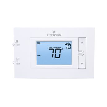
THERMOSTAT OVERVIEW
Before you begin using your thermostat, you should be familiar with its features, display and the location/operation of the thermostat buttons and switches
THERMOSTAT BUTTONS AND SWITCHES THE DISPLAY
- Fan Switch
- System Switch 8.) Indicates that the system is running in cool or heat
- Backlight Button (located on the top of the thermostat0)
- Raises Temperature Setting 10.) Low battery indicator *
- Access Menu Options 11.) Temperature setpoint
- Lowers Temperature Setting 12.) Appears when the keypad is locked (to prevent unwanted changes)
- Thermostat is protecting the equipment from short cycling (5-minute delay)
- Indicates that the system is running in cool or heat
- Battery status indicator
- Low battery indicator *
- Temperature setpoint
- Appears when the keypad is locked (to prevent unwanted changes)
- Next (Menu button) is used to navigate within a menu
- SEE TROUBLESHOOTING

* Whenever “ Replace ” appears in the display, new premium brand AA alkaline batteries should be installed. If the house will be unoccupied for an extended period and either “ ” or “ Replace ” is displayed, install new batteries before leaving.
USER MENU
To customize thermostat settings, press and hold the Menu button for ½ second from the home screen. Use the Next button to advance through menu items. Press or to change the setting.

- Keypad Lockout – To prevent unwanted changes, the buttons can be disabled. To turn this feature On, press and hold and the Menu button until the icon appears (this can also be turned on in the menu). To turn Off, press and hold and the Menu button for 3 seconds.
TROUBLESHOOTING


Resetting the Thermostat or Thermostat Settings
- If the thermostat has good batteries, but has a blank display or does not respond to key presses, the thermostat should be reset by removing the batteries for 2 minutes. This reset will not change the menu settings. If the condition persists after reinstalling the batteries, replace the thermostat.
- To conveniently reset only the user settings back to factory defaults, press Menu and Backlight buttons at the same time and hold until the display goes blank and resets.
WARNING: This product contains a chemical known to the state of California to cause
cancer and birth defects and other reproductive harm
REFERENCE
https://www.emerson.com/en-us/global
https://climate.emerson.com/documents/1f83c-11np-installation-instructions-en-1594392.pdf
