INNOVA OBD2 Car Scan and Code Reader Tool User Manual
SAFETY FIRST!
This manual describes common test procedures used by experienced service technicians. Many test procedures
require precautions to avoid accidents that can result in personal injury, and/or damage to your vehicle or test equipment.
- When an engine is running, it produces carbon monoxide, a toxic and poisonous gas. To prevent serious injury or death from carbon monoxide poisoning, operate the vehicle ONLY in a well-ventilated area.
- To protect your eyes from propelled objects as well as hot or caustic liquids, always wear approved safety eye protection.
- When an engine is running, many parts (such as the coolant fan, pulleys, fan belt etc.) turn at high speed. To avoid serious injury, always be aware of moving parts.
- Keep a safe distance from these parts as well as other potentially moving objects.
- Engine parts become very hot when the engine is running.
- To prevent severe burns, avoid contact with hot engine parts.
CONTROLS AND INDICATORS
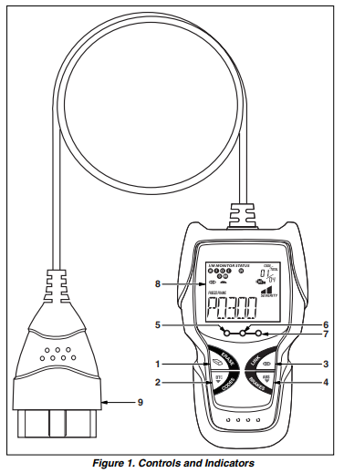
- ERASE button: Erases Diagnostic Trouble Codes (DTCs) and “Freeze Frame” data from your vehicle’s computer, and resets Monitor status.
- DTC button: Displays the Diagnostic Trouble Codes View screen and/or scrolls the LCD display to view Diagnostic Trouble Codes.
- LINK button: When the Code Reader is connected to a vehicle, links the Code Reader to the vehicle’s PCM to retrieve Power train DTCs from the computer’s memory.
- ABS button: Links the Code Reader to the vehicle’s ABS control module to retrieve ABS DTCs from the computer’s memory.
- GREEN LED: Indicates that all engine systems are running normally (all Monitors on the vehicle are active and performing their diagnostic testing, and no DTCs are present).
- YELLOW LED: Indicates there is a possible problem. A “Pending” DTC is present and/or some of the vehicle’s emission monitors have not run their diagnostic testing.
- RED LED: Indicates there is a problem in one or more of the vehicle’s systems. DTCs are shown on the Code Reader’s LCD display.
- LCD Display: Displays test results, Code Reader functions and Monitor status information. See DISPLAY FUNCTIONS, below, for details.
- CABLE: Connects the Code Reader to the vehicle’s Data Link Connector (DLC).
DISPLAY FUNCTIONS
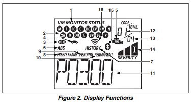
- I/M MONITOR STATUS field: Identifies the I/M Monitor status area.
- Monitor icons: Indicate which Monitors are supported by the vehicle under test, and whether or not the associated Monitor has run its diagnostic testing (Monitor status).
- Link icon: Indicates whether or not the Code Reader is communicating (linked) with the vehicle’s on-board computers. When visible, the Code Reader is communicating with the computers. If the Link icon is not visible, the Code Reader is not communicating with the computers.
- Vehicle icon: Indicates whether or not the Code Reader is being properly powered through the vehicle’s Data Link Connector (DLC). A visible icon indicates that the Code Reader is being powered through the vehicle’s DLC connector.
- MIL icon: Indicates the status of the Malfunction Indicator Lamp (MIL). The MIL icon is visible only when a DTC has commanded the MIL on the vehicle’s dashboard to light.
- ABS icon: Indicates the currently displayed DTC is an Anti-Lock Braking System code.
- HISTORY icon: Indicates the currently displayed DTC is a “History” code.
- FREEZE FRAME icon: Indicates that “Freeze Frame” data has been stored in the vehicle’s computer for the currently displayed DTC.
- PENDING icon: Indicates the currently displayed DTC is a “Pending” code.
- PERMANENT icon: Indicates the currently displayed DTC is a “Permanent” code.
- DTC Display Area: Displays the Diagnostic Trouble Code (DTC) number. Each fault is assigned a code number that is specific to that fault.
- Code Number Sequence: The Code Reader assigns a sequence number to each DTC that is present in the computer’s memory, starting with “01.” This helps keep track of the number of DTCs present in the computer’s memory. Code number “01” is always the highest priority code, and the one for which “Freeze Frame” data
has been stored. - Code Enumerator: Indicates the total number of codes retrieved
- Severity: Indicates the level of severity for the priority code (code number “1”),from the vehicle’s computer.
- Bluetooth icon: Indicates communication status with a compatible Innova mobile application (please visit www.innova.com/apps for more information). When ON, indicates an active Bluetooth connection has been established. When OFF, indicates Bluetooth is not connected.
- WiFi icon: Indicates WiFi communication status. When ON, indicates the scan tool is linked to a WiFi network. When OFF, indicates there is no WiFi connection.
Using the Code Reader
CODE RETRIEVAL PROCEDURE
Never replace a part based only on the DTC definition. Each DTC has a set of testing procedures, instructions and flow charts that must be followed to confirm the location of the problem. This information is found in the vehicle’s service manual. Always refer to the vehicle’s service manual for detailed testing instructions.
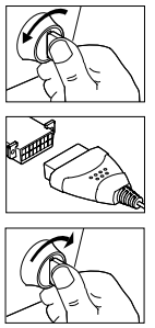
- Turn the ignition off.
- Locate the vehicle’s 16-pin Data Link Connector (DLC).
- Connect the Code Reader’s cable connector to the vehicle’s DLC. The cable connector is keyed and will only fit one way.
- Turn the ignition on. DO NOT start the engine.
- The Code Reader will automatically link to the vehicle’s computer(s).
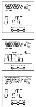
- Read and interpret the Diagnostic Trouble Codes using the LCD display and the green, yellow and red LEDs.
-
- Green LED: Indicates that all engine systems are “OK” and running normally. All monitors on the vehicle are active and are performing their diagnostic testing, and no trouble codes are present. The message 0 DTC will show on the Code Reader’s LCD display for further confirmation.
- MONITOR STATUS: If the Code Reader’s LCD display shows the message 0 DTC (indicating there are
no DTCs present in the vehicle’s computer), but the yellow LED is lit, it indicates a “Monitor Has Not Run” status. This means that some of the Monitors on the vehicle have not yet finished their diagnostic self-testing.
VIEWING ABS DTCs
- If not connected already, connect the Code Reader to the vehicle’s DLC, and turn the ignition “On.”
- Perform the Code Retrieval procedure as described on page 7.
- Press the ABS button. After 4-5 seconds, the Code Reader will retrieve and display any Diagnostic Trouble
- Codes If more than one code is present, press and release the ABS button, as necessary, to display additional codes.
- When the last retrieved DTC has been displayed and the ABS button is pressed, the Code Reader returns to the “Priority” code.stored in the ABS controller’s memory.
Accessing Repair Solutions
- Download and install the Repair Solutions 2® app from the App Store (for iOS devices) or Google Play (for Android devices).
- Launch the Repair Solutions 2 app and log in to your account.
- Connect the Code Reader to a vehicle and establish a Bluetooth or WiFi connection with your Smart Device (refer to CONNECTING TO BLUETOOTH / WIFI, below). Be sure your Smart Device is connected to an available WiFi network. The Repair Solutions 2 app will store three WiFi configurations only.
- Retrieve diagnostic data (refer to CODE RETRIEVAL PROCEDURE on 7 for details).
- The Repair Solutions 2 app automatically displays a report based on the retrieved diagnostic data. If the Code Reader is not connected to WiFi or Bluetooth, vehicle data will not be saved.
CONNECTING TO BLUETOOTH / WIFI
Launch the Repair Solutions 2 app and follow the prompts to establish Bluetooth and (optionally) WiFi connections, as follows:
- Launch the Repair Solutions 2 app. Select Wifi Tools Settings from the menu.
- When Bluetooth pairing is complete, a confirmation screen displays. Click Continue.If a Bluetooth connection cannot be established, an advisory message displays. Tap Try Again to repeat the pairing process.
- Follow the on-screen prompts to connect to an available WiFi network. You can automatically connect to the network your Smart Device is currently connected to, or you can manually connect to another available network.
- When WiFi pairing is complete, a confirmation screen displays. Click Continue to view the “Setup p Complete” message, then click Continue to enter Repair Solutions 2.
-
- If a WiFi connection cannot be established, an advisory message displays.
LIMITED ONE YEAR WARRANTY
The Manufacturer warrants to the original purchaser that this unit is free of defects in materials and workmanship under normal use and maintenance for a period of one (1) year from the date of original purchase. If the unit fails within the one (1) year period, it will be repaired or replaced, at the Manufacturer’s option, at no charge, when returned prepaid to the Service Center with Proof of Purchase. The sales receipt may be used for this purpose. Installation labor is not covered under this warranty. All replacement parts, whether new or remanufactured, assume as their warranty period only the remaining time of this warranty.