Maono WM821 Dual Wireless Microphone System User Manual
Key operation and LED lighting instructions
Buttons (Transmitter TX1 & TX2)
- Power On/Off Button U – Long press for at least 3 seconds to turn on or off the device.Short press to mute or unmute.
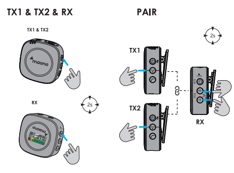
- Pair Button (g – Long press for more than 3 seconds to start the connection function.
- Low cut button © – Short press to turn on or off the low cut function.
- RESET Reset button (transmitter TX1 & TX2)-when the transmitter starts to connect to receivers but failed to get connected, please use the SIM card pin. Insert it into the
- RESET hole and press reset button for 3 seconds, the transmitter will automatically restart, then please try to connect again.
Connector (Transmitter TX1 & TX2)
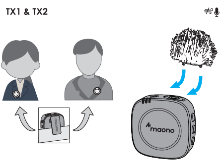
External microphone 3.5mm input jack — When an external microphone is plugged in, the transmitter automatically switches to external microphone input. 4 charging contacts
LED Indicator (Transmitter TX1 & TX2 & RX)
Connection indicator :
- Solid – connected: Flash – disconnected : Rapid Flash connecting
- Turn on the power on the transmitter and the LED will flash. Then turn on the power button on RX receiver, and WM821 will automatically pair the transmitter to the receiver and the LED will remain solid.
Battery LED Indicator :
- No lights= internal battery is above 20%
- Red flashing LED=internal battery is below 20%
- Solid Red LED=charging. Once fully charged, the red light will turn off.
Buttons (Receiver RX)
- Power/Mode Switch Button C – Long press for 3 seconds to turn receiver on and off. Short press to switch between Mixed channels/stereo mode, and the output A/B or MIX display will appear on the screen.
- Launch Volume control @ – (Short press) Cycle through 6 levels to control the volume.
- Launch (2) Volume control B – (Short press) Cycle through 6 levels to control the volume.
- Pairing function 90- To activate the paring function on the receiver, you need to press and hold the volume A+ B button at the same time for more than 3 seconds A/B paring icon* will flash in pairing.It og will turn to solid on when the receiver is connected to the receiver.
- RESET Reset button (receiver RX)-when the receiver start: to connect to transmitters but failed to get connect- ed.please use the SIM card pin. Insert it into the RESET hole and press reset button for 3 seconds, the receiver will automatically restart, then please try to connect again.
Connector (Receiver RX)
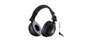
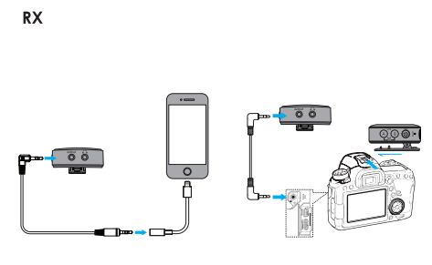
OUTPUT audio output port-3.5mm TRS interface Headphone interface-connect headphones to monitor the transmitter’s live audio Charging contacts-4 gold contacts
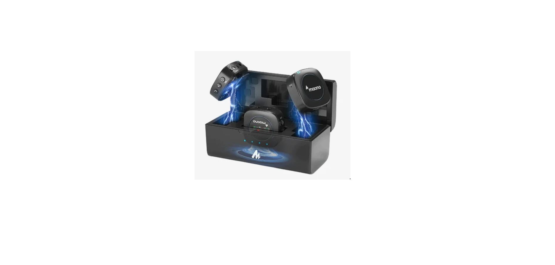
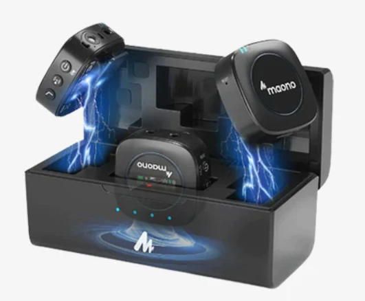
Charging case
LED indicator (charging case)
- 4 solid lights: >90% power
- 3 solid lights: >65% power
- 2 solid lights: >40% power
- 1 solid light: >15% power
- 1 blinking light: <15% power
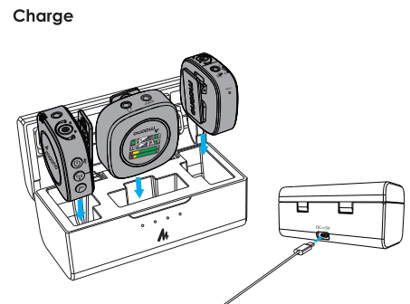
Note: TX and RX will turn themselves off automatically when put in charging case. To supply power to the charging box, please choose a power adapter with an output of 5V=-=1.5A or more.
Technical Specification
Transmission Type 1540%01
Polar Pattern (Built-in Mic)
Built-in Mic frequency response
External Mic frequency response 977=3500,3010 5
Maximum Output Level #
Maximum SPL *75
Battery Capacity AT (EAR
Charge port 3640
Battery Life :
Audio Input 2409m A
Audio Output 2104nd
2.4GHz Wireless 2.4G 74
80Hz -16kHz
50Hz -18kHz
Line output:-10dBu ; Headphone output:3.2dBu
105dB SPL |
0.90%
Line output:75dB; Headphone output: 80dB
350mAh/3.7V (##) ;
2500mAh/3.7V (76/1)|
TYPE-C, DC 5V
3.5mm TRS lavalier microphone input (Transmitter)
3.5mm TRS
3.5mm TRS (Receiver)
3.5mm TRST7L (#5488)
FCC Statement
This device complies with Part 15 of the FCC Rules. Operation is subject to the following two conditions:
- This device may not cause harmful interference, and
- This device must accept any interference received, including interference that may cause undesired operation.
Warning: Changes or modifications not expressly approved by the party responsible for compliance could void the user’s authority to operate the equipment.
Note
This equipment has been tested and found to comply with the limits for a Class B digital device, pursuant to Part 15 of the FCC Rules. These limits are designed to provide reasonable protection against harmful interference in a residential installation. This equipment generates uses and can radiate radio frequency energy and, if not installed and used in accordance with the instructions, may cause harmful interference to radio communications. However, there is no guarantee that interference will not occur in a particular installation. If this equipment does cause harmful interference to radio or television reception, which can be determined by turning the equipment off and on, the user is encouraged to try to correct the interference by one or more of the following.
Measures
- Reorient or relocate the receiving antenna.
- Increase the separation between the equipment and receiver.
- Connect the equipment into an outlet on a circuit different from that to which the. receiver is connected.
- Consult the dealer or an experienced radio/TV technician for help.
REFRENCE LINK