Table of contents
show
Panasonic SF-C13 Control Unit Exclusive

OUTLINE
- This product is a control unit exclusive for the light curtain conforming to European / North American safety standards and Japanese safety standards for press machines.
- This device complies with the following standards / regulations. EU Machinery Directive 2006/42/EC EMC Directive 2014/30/EU RoHS Directive 2011/65/EU EN 61496-1 (Type 4), EN 55011, EN IEC 63000 EN ISO 13849-1: 2015 (Category 4, PLe) IEC 61496-1 (Type 4), ISO 13849-1: 2015 (Category 4, PLe) JIS B 9704-1 (Type 4), JIS B 9705-1 (Category 4) ANSI/UL 61496-1 (Type 4), ANSI/UL 508, UL 1998 (Class 2) CAN/CSA C22.2 No.14, CAN/CSA C22.2 No.0.8 OSHA 1910.212, OSHA 1910.217(C), ANSI B11.1 to B11.19, ANSI/RIA 15.06 Regarding EU Machinery Directive, a Notified Body, TÜV SÜD, has certified with the type examination certificate. With regard to the standards in US / Canada, a NRTL, UL (Underwriters Laboratories Inc.) has certified for CULUS Listing Mark. S1-G-35-2005, S2-W-11-2003 The S-mark certificate has been certified by Korea Occupational Safety & Health Agency (KOSHA).
FUNCTIONAL DESCRIPTION

INSTALLATION POSITION / DIRECTION / METHOD
- Use the 35mm width DIN rail to install the unit.
- The installation position / direction is not basically limited.
- Please fix this product with the DIN rail stopper MS-DIN-E (optional) after installing the product on to the 35mm width DIN rail.
- If two or more units are placed side by side, make sure to space them at least 5mm apart. In case they are mounted close to each other, lower the rated operation current of the safety output depending on the ambient temperature, referring the right graph
- Always install this product in a control panel having an IP54 or higher protective structure.


I/O CIRCUIT DIAGRAMS

- The following cables are recommended for power supply / output line and signal line. Solid wire: ø0.4 to ø1.2mm (AWG 26 to 16) Twisted wire: 0.2 to 1.25mm2 (AWG 24 to 16) Standard stripped wire length: 11mm
- For wiring the light curtain, refer to the instruction manual enclosed with the light curtain.
- When connecting a product other than this product with the light curtain, arrange a terminal block separately.
- The figure shown below is the case that this product is connected to a type 4 PNP output type SF4D series. Connect the contr
- In case of connecting a type 2 PNP output type SF2C series, connect the control output (OSSD) of SF2C series to S1, and also put a jumper between S2 and S3.
- The figure shown below is the case that this product is connected to a type 4 NPN output type SF4D series. Connect the control output OSSD 1 and OSSD 2 of SF4D series to S4 and S2 respectively.
- In case of connecting a type 2 NPN output type SF2C series, connect the control output (OSSD) of SF2C series to S4, and also put a jumper between S2 and S3.
Auto reset
- In case of the auto reset, configure the back check circuit between X1 and X3.
- If it is not necessary to check KA and KB, short-circuit between X1 and X3.
- Do not connect anything to X2.
- Avoid auto-reset of the system after emergency stop by using the other control circuit. (IEC / EN 60204-1 part 9.2.5.4.2 and 10.8.3)
MOUNTING TERMINAL BLOCK
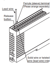
- When connecting to the terminal block, insert a solid wire or twisted wire (lead wire) with a ferrule (sleeve) terminal (please arrange separately into the hole till it stops as shown in the figure right. The wire is locked when it is properly inserted. However, do not to pull the wire with excessive force, as this can cause a cable break.
- When connecting the twisted wire (lead wire) without a ferrule (sleeve) terminal, insert the wire to the innermost of the connecting hole while pressing the release button.
- When releasing the solid wire or the twisted wire (lead wire), pull the wire while pressing the release button
- The following solid wire and twisted wire (lead wire) are recommended. Solid wire: ø0.4 to ø1.2mm (AWG 26 to 16) Twisted wire (lead wire): 0.2 to 1.25mm2 (AWG 24 to 16) Standard stripped wire length: 11mm
SHORT-CIRCUIT PROTECTION
- The power supply unit of this equipment adopts the electronic fuse which do not require any replacement.
- When the electronic fuse is operated, turn OFF the power supply, and remove the cause of overcurrent before restarting the power supply for resetting.
- The electronic fuse is not suitable to use in which the equipment is operated continuously or daily. Note that operating the equipment continuously may be unable to satisfy the specifications.
FUNCTIONS
- Trailing edge switching function
- This function is to accept the input when the reset switch is pressed (contact “close”) and then released (contact “open”) at the manual start setting. An unexpected start-up due to the welded reset switch can be avoided.
MAINTENANCE
- Be sure to do maintenance before use and 6 month periodic maintenance. Refer included instruction manual of light curtain for the inspection items.
- In case replacing this device to new this device, be sure special technician to exchange it. And do daily maintenance and periodic maintenance.
USING THIS PRODUCT AS A SAFETY EQUIPMENT FOR A PRESS MACHINE IN JAPAN
- When used in combination with SF4D-□-01 / SF4B-□-01, this product satisfies the “Model Examination” as set forth in the Japanese Industrial Safety and Health Laws Provision 44-2 as indicated below.
- Conforming standards: Standards for press machine or shear safety equipment structure (Ministry of Labor Notice No. 102, issued September 21, 1978)
- When using SF4D-□-01 / SF4B-□-01 and this product as safety equipments for a press machine in Japan, a pre-work inspection and periodic inspection must be carried out by the press machine work supervisor or by the person in charge of the matters listed in Provision 134, No. 1, 2 and 4 of the Ordinance on Labor Safety and Hygiene. The press machine work supervisor, etc., must inspect the following matters before starting work, and must record and save the results. Emitter of SF4D-□-01 / SF4B-□-01 □ Security of mounting □ Adequacy of mounting position (safety distance and vertical position) □ Presence of damage □ Presence of abnormality in external wires □ Presence of contamination on emitter □ Security of detection state Receiver of SF4D-□-01 / SF4B-□-01 □ Security of mounting □ Adequacy of mounting position (safety distance and vertical position) □ Presence of damage □ Presence of abnormality in external wires □ Presence of contamination on receiver □ Security of detection state Control unit SF-C13 □ External wiring □ Indicators □ Presence of abnormal operation with switches, etc. □ Security of mounting For details, refer to “About the Revision of the Safety Device Management Guidelines for Press Machines” (Ministry of Health, Labor and Welfare Publication 0930 No. 11, September 30, 2015).
- Compatible press machines • When using this product as a safety equipment for a press machine in Japan, the machine in which SF4D-□-01 / SF4B-□-01 and this product are mounted must be capable of suddenly stopping from any operation point even during the operation cycle. Do not use SF4D-□-01 / SF4B-□-01 and this product with a machine having an irregular sudden stop. • Do not use this product with a power press having a full-rotation clutch.
- When using this product as a safety equipment for a press machine in Japan, do not use the product with a press machine that does not satisfy the following specifications
TROUBLESHOOTING
- The number of times the fault indicator (yellow) blinks indicates the type of error state, as follows

- Make sure that this product and the light curtain are connected to the common power supply.
- When the sensor doesn’t operate properly even if the remedies described above are taken, contact our office.
- Interval of blinking for the fault indicator (yellow) is approx. 0.6 sec. Check the number of times the indicator blinks for approx. 2 sec. from
the indicator “OFF” period.

SPECIFICATIONS
- gut Approx. 200g Notes: 1) Timing chart of the safety output is diagram below.
- Light received
- Light blocked
- Light received status
- Response time of Light curtain
- ON
- OFF
- ON
- OFF
- Control output 1 / 2 (OSSD
- 1 / 2) of light curtain
- Safety input of this device
- 10ms or less
- 2) The lifetime of the switch of relay depends on type of the load, frequency of
- switching or environment etc.
- 3) Mean cycle time that 10% of parts reach dangerous failure.
CAUTIONS
- In case this unit is connected to a product other than the connectable input devices, this unit doesn’t meet the control category 4 specified in ISO 13849-1: 2015 (EN ISO 13849-1: 2015).
- This product has been developed / produced for industrial use only.
- Make sure that the power is OFF while wiring.
- Take care that wrong wiring will damage the product.
- Verify that the supply voltage variation is within the rating.
- Take care that if a voltage exceeding the rated range is applied, or if an AC power supply is directly connected, the product may get burnt or damaged.
- The DC power supply unit must satisfy the conditions given below:
- Power supply unit authorized in the region where this device is to be used.
- Power supply unit SELV (safety extra low voltage) / PELV (protected extra low voltage) conforming to EMC Directive and Low-voltage Directive (In case CE Marking conformity is required.)
- Power supply unit conforming to the Low-voltage Directive and with an output of 100VA or less.
- The frame ground (F.G.) terminal must be connected to ground when using a commercially available switching regulator.
- Power supply unit with an output holding time of 20ms or more.
- In case a surge is generated, take countermeasures such as connecting a surge absorber to the origin of the surge.
- Power supply unit corresponding to CLASS 2 (only for requiring CULUS Mark conformation).
- Do not run the wires together with high-voltage lines or power lines or put hem in the same raceway. This can cause malfunction due to induction.
- Avoid dust, dirt, and steam.
- Take care that the product does not come in contact with water, oil, grease, or organic solvents such as thinner, etc.
- The seal as shown in the drawing on the right is stuck to the engagement point of unit. When the seal is peeled off or broken, this equipment will not be certified as a “Safety equipment” and will not be covered by our guarantee.
- Note that this equipment is applicable only in the control circuit grounded in accordance with IEC 60204-1 and JIS B 9960-1, or in the control circuit in
which the insulation monitor unit (ground fault detection unit) is arranged. - This product is suitable for indoor use only.
DIMENSIONS (Unit: mm)

INTENDED PRODUCTS FOR CE MARKING
● The model listed under “ SPECIFICATIONS” comes with CE Marking. As for all other models, please contact our office.
CE MARKING DECLARATION OF CONFORMITY

Panasonic Industrial Devices SUNX Co., Ltd.
https://panasonic.net/id/pidsx/global
Download Pdf Link
https://manuals.plus/m/17f558ae3dd73e28c282808e9cf5decab9995e8f330951783baa02de78952fb0_optim.pdf