Panasonic TPF Series Conductive Capacitors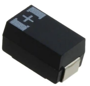
Features
- Super low ESR (5 mΩ max.)
- Large capacitance (1000 μF max.)
- RoHS compliance, Halogen free
Specifications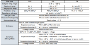
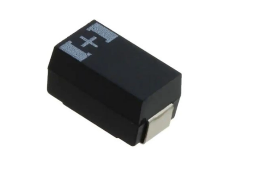
Marking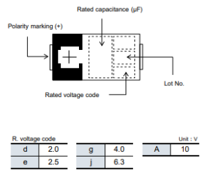
Dimensions (not to scale)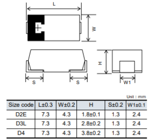
Characteristics list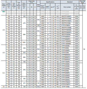
- Ripple current (100 kHz / +45 ℃)
- ESR (100 kHz / +20 ℃)
- tan δ (120 Hz / +20 ℃)
- After 5 minutes
◆ Please refer to each page in this catarog for “Reflow conditions” ,“Taping specifications” and “Floor life level” .
◆ Small order quantity (500 pcs/reel) is available with TPF series. Please contact our sales representative if you prefer it
Guidelines and precautions regarding the technical information and use of our products described in this online catalog.
- If you want to use our products described in this online catalog for applications requiring special qualities or reliability, or for applications where the failure or malfunction of the products may directly jeopardize human life or potentially cause personal injury (e.g. aircraft and aerospace equipment, traffic and transportation equipment, combustion equipment, medical equipment, accident prevention, anti-crime equipment, and/or safety equipment), it is necessary to verify whether the specifications of our products fit to such applications. Please ensure that you will ask and check with our inquiry desk as to whether the specifications of our products fit to such applications use before you use our products.
- The quality and performance of our products as described in this online catalog only apply to our products when used in isolation. Therefore, please ensure you evaluate and verify our products under the specific circumstances in which our products are assembled in your own products and in which our products will actually be used.
- Please ensure the safety by means of protection circuit, redundant circuit etc. in your system design in order to prevent the occurrence of life crisis and other serious damages due to the failure of our products.
- The products and product specifications described in this online catalog are subject to change for improvement without prior notice. Therefore, please be sure to request and confirm the latest product specifications which explain the specifications of our products in detail, before you finalize the design of your applications, purchase, or use our products.
- The technical information in this online catalog provides examples of our products’ typical operations and application circuits. We do not guarantee the non-infringement of third party’s intellectual property rights and we do not grant any license, right, or interest in our intellectual property.
- If any of our products, product specifications and/or technical information in this catalog is to be exported, the laws and regulations of the exporting country, especially with regard to security and export control, shall be observed.
- The switchover date for compliance with the RoHS Directive/REACH Regulations varies depending on the part number or series of our products.
- When you use the inventory of our products for which it is unclear whether those products are compliant with the RoHS Directive/REACH Regulation, please select “Sales Inquiry” in the website inquiry form and contact us. Please note that we do not owe any liability and responsibility if our products are used beyond the description of this catalog or without complying with precautions in this catalog. Please note that we do not owe any liability and responsibility if our products are used beyond the description of this catalog or without complying with precautions in this catalog.
Notices
■ Applicable laws and regulations
- This product complies with the RoHS Directive (Restriction of the use of certain hazardous substances in electrical and electronic equipment (DIRECTIVE 2011/65/EU and(EU)2015/863)).
- No Ozone Depleting Chemicals(ODC’s), controlled under the Montreal Protocol Agreement, are used in producing this product. We do not use PBBs or PBDEs as brominated flame retardants.
- Follow export procedures in accordance with the Foreign Exchange and Foreign Trade Law and other export-related laws and regulations when exporting this product.
- These products are not dangerous goods on the transportation as identified by UN(United Nations) numbers or UN classification.
■ Limited applications
- This capacitor is designed to be used for electronics circuits such as audio/visual equipment, home appliances, computers and other office equipment, optical equipment, measuring equipment.
- An advanced specification must be signed individually for high-reliability use that might threaten human life or property due to a malfunction of the capacitor.
■ Intellectual property rights and licenses
- The technical information in this specification provides examples of our products’ typical operations and application circuits. We do not guarantee the non-infringement of third party’s intellectual property rights and we do not grant any license, right, or interest in our intellectual property.
Items to be observed
■ For specification
- This specification guarantees the quality and performance of the product as individual components. The durability differs depending on the environment and the conditions of usage. Before use, check and evaluate their compatibility with actual conditions when installed in the products. When safety requirements cannot be satisfied in your technical examination, inform us immediately.
- Do not use the products beyond the specifications described in this document.
■ Upon application to products where safety is regarded as important
- If a malfunction of this product may result in the loss of human life or other serious damage, in traffic transportation equipment (trains, automobiles, traffic signals, etc.), medical equipment, aerospace equipment, electric heating equipment, combustion and gas equipment, rotating equipment, disaster prevention and security equipment, etc., ensure safety by giving sufficient consideration to a fail-safe design, for example, by considering the following items.
- The system is equipped with a protection circuit and protection device.
- The system is equipped with a redundant circuit or other system to prevent an unsafe status in the event
of a single fault.
■ Conditions of use
- Before using the products, carefully check the effects on their quality and performance, and determined whether or not they can be used. These products are designed and manufactured for general-purpose and standard use in general electronic equipment. These products are not intended for use in the following special conditions.
- In liquid, such as Water, Oil, Chemicals, or Organic solvent.
- In direct sunlight, outdoors, or in dust.
- In vapor, such as dew condensation water of resistive element, or water leakage, salty air, or air with a highconcentration corrosive gas, such as Cl2, H2S, NH3, SO2, or NOx.
- In an environment where strong static electricity or electromagnetic waves exist.
- Mounting or placing heat-generating components or inflammables, such as vinyl-coated wires, near these products.
- Sealing or coating of these products or a printed circuit board on which these products are mounted, with resin and other material.
- Using resolvent, water or water-soluble cleaner for flux cleaning agent after soldering. (In particular, when using water or a water-soluble cleaning agent, be careful not to leave water residues)
- Using in the atmosphere where strays acid or alkaline.
- Using in the atmosphere where there are excessive vibration and shock.
- Using in the atmosphere where there are low pressure or decompression.
・ Please arrange circuit design for preventing impulse or transitional voltage.
Ensure that the voltage is lower than the rated voltage in the following condition: shock voltage circuits, transient phenomena in which excessive high voltage is applied in a short period of time, or when pulse high voltage is applied.
・ Our products there is a product are using an electrolyte solution. Therefore, misuse can result in rapid deterioration of characteristics and functions of each product. Electrolyte leakage damages printed circuit and affects performance, characteristics, and functions of customer system.
Application Guidelines (POSCAP
1. Circuit design
1.1 Prohibited circuits
Since problems can be expected, POSCAP cannot be used on the following circuits.
- High impedance voltage retention circuits
- Coupling circuit
- Time constant circuits
- Circuits greatly affected by leakage current
- The circuit in which two or more POSCAP are connected in a series so as to raise the endurance voltage.
1.2 Failure and life-span
The failure rate is 0.5 %* / 1000 h (Confidence level : 60 %) based on JIS C 5003.
The mainly failure modes are as follows.
* B2 size or less : 1.0 %
1.2-1 Contingency failure
The main causes of failure are thermal stresses cause by the soldering or thermal use environment, along with heat stresses, electrical stresses or mechanical stresses. The most common failure mode is a short circuit. In case a short circuit occurs, ensure safety by fully considering the followings.
(a) If POSCAP emit smoke, turn off the main power of the equipment. In this case, keep your face and hands away from the area.
(b) It may take a few seconds to a few minutes before POSCAP emits smoke by the situation. When using a protection circuit, design the product so that it operates during this period.
(c) If the smoke comes into eyes, rinse immediately. If the smoke is inhaled, gargle immediately.
(d) In case a large current continues to flow after a short circuit, in the worst case, the shorted-out section may ignite. Consider safety designs such as redundant design and protection circuits.
1.2-2 Wear-out failure (lifetime)
When lifetime exceeded the specified guarantee time of Endurance and Damp heat, electrolyte might insulate and cause electric characteristic changed. This is called an open circuit. The rated capacitance values and the electrical characteristics values such as ESR specified in the characteristics list are factory default values. Please carefully design a circuit since rated capacitance values and the electrical characteristics values may change (increase) beyond the specified values under the conditions of rated voltage/temperature and electrical/mechanical performances.
1.3 Reduction of failure stress
When POSCAP is used within the rated voltage, it shows a stable characteristic, but it may be damaged in a short circuit when an overvoltage, for instance, is applied. The time to reach the failure mode can be extended by using POSCAP with reduced environment temperature, ripple current and applied voltage. Failure rate
- In the case of the endurance which is 105 °C 2000 h.
- 0.5 %/1000 h (Environment temp. : 105 °C, Rated voltage or Category voltage applied)
- In the case of the endurance which is 105 °C 1000 h or 125 °C 1000 h.
- 1.0 %/1000 h (Environment temp. : 105 °C, Rated voltage or Category voltage applied)
- In the case of the endurance which is 85 °C 1000 h.
- 1.0 %/1000 h (Environment temp. : 85 °C, Rated voltage applied)
1.4 Check the rated performance
After checking the operation and installation environments, design the circuit so that it falls within the rated performance range stipulated in this delivery specification.
1.5 Operating temperature and ripple current
- Set the operating temperature so that it falls within the range stipulated in this delivery specification.
- Do not apply current that exceeds the allowable ripple current. Ripple current should be controlled so that surface temperature of a capacitor do not exceed the rated temperature. (For questions regarding TQC series, please contact us.)
- The ESR values specified in the characteristics list are factory default values.
ESR values may change (increase) beyond the specified values depending on the customer’s use conditions
1.6 Leakage current
Even when the soldering conditions fall within the range of this delivery specifications, leakage current increases a little on occasion. It also increases a little during high temperature storage, high humidity storage こand temperature cycling with no voltage applied. In cases such as these, leakage current will decrease by applying voltage under the condition of below the POSCAP’s maximum operating temperature. The speed at which the leakage current is restored is increased by applying voltage when the POSCAP’s temperature is close to the maximum operating temperature.
1.7 Rapid charge and discharge limitation
Rapid charge and discharge are restricted (for maintenance of high-proof reliability). A protective circuit is recommended for when a rapid charge or discharge causes excessive rush current since this is main cause of short circuit and large leakage current. Use a protective circuits in case the rush current value exceeds 20 A*. Be sure to insert a protection resistor of about 1 kΩ for charge and discharge when measuring the leakage current.
* When TH series use under the ambient temperature more than 105 °C : 10 A, TPU series : 10 A
2. Mounting
2.1 Protect circuit
The failure mode of POSCAP is the short mode. When it breaks down, short electric current flows to it. POSCAP gives off heat by this short current.
Do the following consideration in design fully for the safety because it has a bad influence on the part around POSCAP due to this heat.
- A protective circuit and a protective device are set up, so as to make the system safer.
- A diffuse circuit and so on is set up, so as to make the system safer such as that a machine may not break down as to the single trouble.
2.2 Considerations when soldering
The soldering conditions are to be within the range prescribed in this delivery specification. If the specifications are not followed, there is the possibility of degradation of electric characteristic and lifetime when soldering is conducted under conditions that are harsher that those stipulated.
2.3 Others
POSCAP’s Electrical characteristics are affected by temperature and frequency fluctuations. Design circuits after checking the amount of fluctuation.
3. Storage
It is necessary to set an environment to prevent a trouble at the time of soldering by the degradation of solder ability or moisture’s getting into the molding resin when POSCAP are stored.
- Please make storage of POSCAP sealing up in the reel and the moisture proof bag at the time of delivery in the following environment. Also, set storage period of unopened as 18 months or shorter after shipment from factory.
- Room temperature and room humidity (generally : 15 to 35 °C, 45 to 75% RH ) are desirable.
- Place where POSCAP is not exposed by direct sunshine.
- Please unseal the moisture proof bag just before mounting and use up POSCAP in the moisture proof bag. Storage conditions after opening the moisture proof bag are as follows.
POSCAP is not compatible with JEDEC J-STD-020, J-STD-033
✽ Intellectual property right
We, Panasonic Group are providing the product and service that customers can use without anxiety, and are working positively on the protection of our products under intellectual property rights. Representative patents relating to POSCAP are as follows: US Patent No.6508800, No.6891717, No.
download pdf
https://manuals.plus/m/3eacf0c0084fe2381cb129169a1350ef4bcc5997ec5d5a15591fc6b5e60d77db_optim.pdf