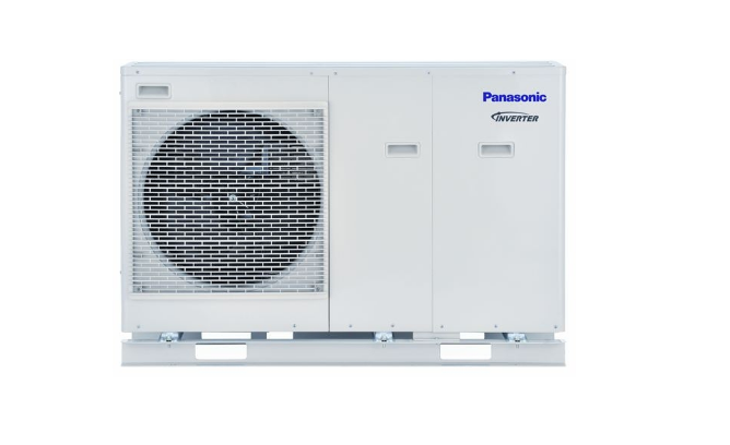
Panasonic UX09*E5 Series Heat Pump Installation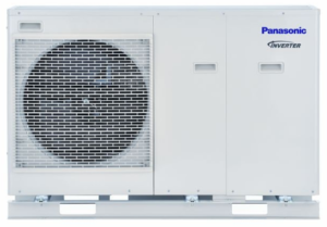
Required tools for Installation Works
- Philips screw driver
- Level gauge
- Electric drill, hole core drill (ø70 mm)
- Hexagonal wrench (4 mm)
- Spanner
- Pipe cutter
- Reamer
- Knife
- Gas leak detector
- Measuring tape
- Thermometer
- Megameter
- Multimeter
- Torque wrench
- Vacuum pump
- Gauge manifold
SAFETY PRECAUTIONS
• Read the following “SAFETY PRECAUTIONS” carefully before installation.
• Electrical work must be installed by a licensed electrician. Be sure to use the correct rating and main circuit for the model to be installed.
• The caution items stated here must be followed because these important contents are related to safety. The meaning of each indication used is as below. Incorrect installation due to ignoring of the instruction will cause harm or damage, and the seriousness is classified by the following indications.
• Please leave this installation manual with the unit after installation.
WARNING This indication shows the possibility of causing death or serious injury.
CAUTION This indication shows the possibility of causing injury or damage to properties only.
The items to be followed are classified by the symbols:
Symbol with white background denotes item that is PROHIBITED from doing.
Symbol with dark background denotes item that must be carried out.
• Carry out test run to confirm that no abnormality occurs after the installation. Then, explain to user the operation, care and maintenance as stated in instructions. Please remind the customer to keep the operating instructions for future reference.
WARNING
- Do not install outdoor unit near handrail of veranda. When installing outdoor unit at veranda of high rise building, child may climb up to outdoor unit
- and cross over the handrail and causing accident.
- Do not use unspecified cord, modified cord, joint cord or extension cord for power supply cord. Do not share the single outlet with other electrical
- appliances. Poor contact, poor insulation or over current will cause electrical shock or fi re.
- Do not tie up the power supply cord into a bundle by band. Abnormal temperature rise on power supply cord may happen.
- Do not insert your fingers or other objects into the unit, high speed rotating fan may cause injury.
- Do not sit or step on the unit, you may fall down accidentally.
- Keep plastic bag (packaging material) away from small children, it may cause suffocation.
- Do not use pipe wrench to install refrigerant piping. It might deform the piping and cause the unit to malfunction.
- Do not purchase unauthorized electrical parts for installation, service, maintenance and etc.. They might cause electrical shock or fi re.
- Do not modify the wiring of outdoor unit for installation of other components (i.e. heater, etc.). Overloaded wiring or wire connection points may cause electrical shock or fi re.
- Do not add or replace refrigerant other than specified type. It may cause product damage, burst and injury etc.
- For electrical work, follow local wiring standard, regulation and this installation instruction. An independent circuit and single outlet must be used.
- If electrical circuit capacity is not enough or defect found in electrical work, it will cause electrical shock or fi re.
- Engage dealer or specialist for installation. If installation done by the user is defective, it will cause water leakage, electrical shock or fi re.
- This is a R410A model, when connecting the piping, do not use any existing (R22) pipes and fl are nuts. Using such same may cause abnormally high
- pressure in the refrigeration cycle (piping), and possibly result in explosion and injury. Use only R410A refrigerant.
- Thickness for copper pipes used with R410A must be 0.8mm or more. Never use copper pipes thinner than 0.8mm.
- It is desirable that the amount of residual oil is less than 40mg/10m.
- When install or relocate outdoor unit, do not let any substance other than the specified refrigerant, e.g. air etc. mix into refrigerant cycle (piping).
- Mixing of air etc. will cause abnormal high pressure in refrigeration cycle and result in explosion, injury etc.
- Install according to this installation instructions strictly. If installation is defective, it will cause water leakage, electrical shock or fi re.
- Install at a strong and firm location which is able to withstand the set’s weight. If the strength is not enough or installation is not properly done, the
- set will drop and cause injury.
- Do not use joint cable for outdoor connection cable. Use specified outdoor connection cable, refer to instruction 5 CONNECT THE CABLE
- TO THE OUTDOOR UNIT and connect tightly for outdoor connection. Clamp the cable so that no external force will be acted on the terminal. If
- connection or fixing is not perfect, it will cause heat up or fi re at the connection.
- During installation, install the refrigerant piping properly before run the compressor. Operation of compressor without fixing refrigeration piping and
- valves at opened condition will cause suck-in of air, abnormal high pressure in refrigeration cycle and result in explosion, injury etc.
- During pump down operation, stop the compressor before remove the refrigeration piping. Removal of refrigerant piping while compressor is
- operating and valves are opened will cause suck-in of air, abnormal high pressure in refrigerant cycle and result in explosion, injury etc.
- Tighten the fl are nut with torque wrench according to specified method. If the fl are nut is over tightened, after a long period, the fl are may break and
- cause refrigerant gas leakage.
- After completion of installation, confirm there is no leakage of refrigerant gas. It may generate toxic gas when the refrigerant contacts with fi re.
- Ventilate the room if there is refrigerant gas leakage during operation. Extinguish all fi re sources if present. It may cause toxic gas when the refrigerant contacts with fi re.
- Only use the supplied or specified installation parts, else, it may cause unit vibrate loose, water leakage, electrical shock or fi re.
- If there is any doubt about the installation procedure or operation, always contact the authorized dealer for advice and information.
- Select a location where in case of water leakage, the leakage will not cause damage to other properties.
- When installing electrical equipment at wooden building of metal lath or wire lath, in accordance with electrical facility standard, no electrical
- contact between equipment and building is allowed. Insulator must be installed in between.
- Any work carried out on the outdoor unit after removing any panels which is secured by screws, must be carried out under the supervision of
- authorized dealer and licensed installation contractor.
- This unit must be properly earthed. The electrical earth must not be connected to a gas pipe, water pipe, the earth of lightening rod or a telephone.
- Otherwise there is a danger of electrical shock in the event of an insulation breakdown or electrical earth fault in the outdoor unit.
CAUTION - Do not install the outdoor unit at place where leakage of flammable gas may occur. In case gas leaks and accumulates at surrounding of the unit, it may cause fi re.
- Do not release refrigerant during piping work for installation, re-installation and during repairing a refrigeration parts. Take care of the liquid refrigerant, it may cause frostbite.
- Make sure the insulation of power supply cord does not contact hot part (i.e. refrigerant piping) to prevent from insulation failure (melt).
- Do not touch the sharp aluminum fi n, sharp parts may cause injury.
- Do not release refrigerant into the atmosphere. The product contains fluorinated greenhouse gases and that its functioning relies upon such gases.
- Select an installation location which is easy for maintenance.
- Ensure the correct polarity is maintained throughout all wiring. Otherwise, it will cause electrical shock or fi re. Installation work.
- It may need two or more people to carry out the installation work. The weight of outdoor unit might cause injury if carried by one person
Attached accessories
Accessories part
- Drain elbow
- Rubber cap
1 SELECT THE BEST LOCATION
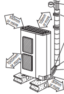
- If an awning is built over the unit to prevent direct sunlight or rain, be careful that heat radiation from the condenser is not obstructed.
Avoid installations in areas where the ambient temperature may drop below -20°C for UD models and -28°C for UX models. - Keep the spaces indicated by arrows from wall, ceiling, fence or other obstacles.
- Do not place any obstacles which may cause a short circuit of the discharged air.
- If outdoor unit installed near sea, region with high content of Sulphur or oily location (e.g. machinery oil, etc.), it lifespan maybe shorten.
- When installing the product in a place where it will be affected by typhoon or strong wind such as wind blowing between buildings, including the rooftop of a building and a place where there is no building in surroundings, fi x the product with an overturn prevention wire, etc. (Overturn prevention fi
Example:
If piping length is 30m, the quantity of additional refrigerant should be 1000g. [(30-10)m x 50 g/m = 1000g]
GWP (R410A) = 2088tting model number: K-KYZP15C)
If piping length is over 10 m, additional refrigerant should be added as shown in the table
INSTALL THE OUTDOOR UNIT
- It is advisable to avoid more than 2 blockage directions. For better ventilation & multiple-outdoor installation, please consult authorized dealer/specialist.
- This illustration is for explanation purposes only.
- After selecting the best location, start installation according to Installation Diagram.
 1. Fix the unit on concrete or rigid frame firmly and horizontally by bolt nut (ø10 mm).
2. When installing at roof, please consider strong wind and earthquake. Please fasten the installation stand fi rmly with bolt or nails.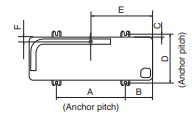
DISPOSAL OF OUTDOOR UNIT DRAIN WATER - When a Drain elbow 1 is used, please ensure to follow below:
– the unit should be placed on a stand which is taller than 50 mm.
– cover the ø20mm holes with Rubber cap 2 (refer to illustration below).
– use a tray (field supply) when necessary to dispose the outdoor unit drain water. - If the unit is used in an area where temperature falls below 0°C for 2 or 3 consecutive days, it is recommended not to use the Drain elbow 1
and Rubber cap 2, for the drain water freezes and the fan will not rotate.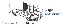
CONNECTING THE PIPING EVACUATION OF THE EQUIPMENT
CAUTION
Do not over tighten, over tightening cause gas leakage
CONNECTING THE PIPING TO OUTDOOR UNIT
Decide piping length and then cut by using pipe cutter. Remove burrs from cut edge. Make flare after inserting the fl are nut (locate at valve) onto the copper pipe. Align center of piping to valves and then tighten with torque wrench to the specified torque as stated in the table. Local pipes can project in any of four directions.
• Make holes in the pipe panels for the pipes to pass through.
• Be sure to install the pipe panels to prevent rain from getting inside the outdoor unit.
[Removing the service panel].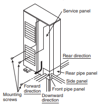
(2) Slide the service panel downward to release the pawls.
After this, pull the service panel toward you to remove it.
CUTTING AND FLARING THE PIPING
- Please cut using pipe cutter and then remove the burrs.
- Remove the burrs by using reamer. If burrs is not removed, gas leakage may be caused. Turn the piping end down to avoid the metal powder entering the pipe.
- Please make flare after inserting the flare nut onto the copper pipes
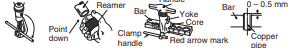
When properly flared, the internal surface of the flare will evenly shine and be of even thickness. Since the fl are part comes into contact with the connections, carefully check the flare finish
EVACUATION OF THE EQUIPMENT
WHEN INSTALLING AN AIR-TO-WATER HEAT PUMP, BE SURE TO EVACUATE THE AIR INSIDE THE UNIT AND PIPES in the following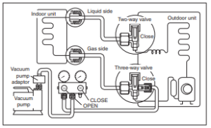 procedure.
- Connect a charging hose with a push pin to the Low side of a charging set and the service port of the 3-way valve.
• Be sure to connect the end of the charging hose with the push pin to the service port. - Connect the center hose of the charging set to a vacuum pump with check valve, or vacuum pump and vacuum pump adaptor.
- Turn on the power switch of the vacuum pump and make sure that the needle in the gauge moves from 0 cmHg (0 MPa) to –76 cmHg (–0.1 MPa). Then evacuate the air approximately ten minutes.
- Close the Low side valve of the charging set and turn off the vacuum pump. Make sure that the needle in the gauge does not move after approximately fi ve minutes.
Note : BE SURE TO FOLLOW THIS PROCEDURE IN ORDER
TO AVOID REFRIGERANT GAS LEAKAGE. - Disconnect the charging hose from the vacuum pump and from the service port of the 3-way valve.
- Tighten the service port caps of the 3-way valve at a torque of
18 N•m with a torque wrench. - Remove the valve caps of both of the 2-way valve and 3-way valve. Position both of the valves to “OPEN” using a hexagonal wrench (4 mm).
- Mount valve caps onto the 2-way valve and the 3-way valve.
• Be sure to check for gas leakage
AIR-TIGHTNESS TEST ON THE REFRIGERATING SYSTEM
Before system charged with refrigerant and before the refrigerating system in put into operation, below site test procedure and acceptance criteria shall be verified by the certified technicians, and/ or the installer:-
Step 1: Pressure test for refrigerant leak detection:
- Steps for pressure test, in accordance to ISO 5149.
- Evacuate the system from refrigerant before the leak test, attach the gauge manifold set correctly and tightly. Charging hose
of Low side connect to Gas side. (Charging hose of High side connect to Liquid side if applicable.) - Adjust the knob on the service valves, and regulator on the gauge set, so that test gas can be inserted through the centre manifold of the gauge set.
- Insert Nitrogen gas into the system through the centre manifold
and wait until the pressure within the system to reach about 1MPa (10 BarG) wait for a few hours and monitor the pressure reading on the gauges. - Please note that the system’s pressure may rise slightly if the test is carried out on mid day, due to temperature rise. The inverse may happen when there is temperature drop at night.
However, this variation will be minimal. - Waiting time depends on the size of the system. Larger systems may require 12 hours of waiting time. Leak detection within smaller system can be achieved in 4 hours.
- Check if there is a constant pressure drop. Move to next step “Step 2: Refrigerant leak detection…” if there is any pressure drop. Otherwise, release the Nitrogen gas and, move to “Step 3: Vacuum test”.
- Next, insert a small amount of same refrigerant into the system through the center hose, until the pressure reaches about 1MPa
(10 Barge).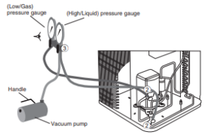
Step 2: Refrigerant leak detection through Electronic halogen leak detector and/or ultrasonic leak detector:
1) Use any one of below detector to check leaking.
i) Electronic halogen leak detector.
i-a) Switch on the unit.
i-b) Cover the test area from direct draft.
i-c) Pass the detection probe near test area and wait for
audible and visible signals.
ii) Ultrasonic Leak Detector
ii-a) Make sure the area is quiet.
ii-b) Switch on the ultrasonic leak detector.
ii-c) Move the probe along your air conditioning system to
test for leaks, and mark for repai
2) Any leak detected at this level shall be repaired and retested, starting from “Step 1: Pressure test”.
NOTE:
– Always recover the refrigerant and Nitrogen gas into recovery cylinder after completion of a test.
– You must use the detection equipment with Detectable Leak Rate of 10-6 Pa.m3 /s or better.
– Do not use refrigerant as test medium for system with total refrigerant charge more than 5kg.
– Test shall be performed with dry Nitrogen or another nonfl ammable, non-reactive, dried gas. Oxygen, air or mixtures containing them shall not be used.
Step 3: Vacuum test:
1) Perform Vacuum test to check leak / moisture if present.
2) Refer to section “EVACUATION OF THE EQUIPMENT” to vacuum gas out of the air conditioning system.
3) Wait for a few hours, depending on the size of the refrigerating system and monitor the pressure rise.
If the pressure rises until 1 bar absolute, then there is leak.
If the pressure rises, but it is lower than 1 bar absolute, then moisture is present.
Next, remove the moisture, or repair, and redo the refrigerant leak testing, starting from “Step 1: Pressure test”.
CONNECT THE CABLE TO THE OUTDOOR UNIT
(FOR DETAIL REFER TO WIRING DIAGRAM AT UNIT)
- Remove the control board cover from the unit by loosening the screw.
- Connecting cable between indoor unit and outdoor unit shall be approved polychloroprene sheathed flexible cable (see below table), type designation 60245 IEC 57 or heavier cable.
- Secure the cable onto the control board with the holder (clamper).
- Attach the control board cover back to the original position with screw
WIRE STRIPPING AND CONNECTING REQUIREMENT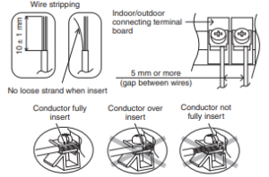
6 PIPE INSULATION
- Please carry out insulation at pipe connection portion as mentioned in Indoor/Outdoor Unit Installation Diagram. Please wrap the insulated piping end to prevent water from going inside the piping.
- If drain hose or connecting piping is in the room (where dew may form), please increase the insulation by using POLY-E FOAM with thickness 6 mm or above.
-
download pdf
- https://manuals.plus/m/d4456cfcc8dc4e87cf379719ae954848fe83c77ee601ab64accd43d265e04c2d_optim.pdf