
Bose Virtually Invisible in-ceiling speakers Manual
Introduction
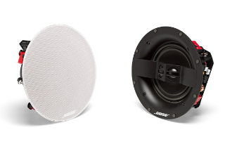
About your Virtually Invisible® 791 series II or 591 in-ceiling speakers
The Bose® Virtually Invisible® 791 series II or 591 in-ceiling speakers provide superior performance for built-in stereo music listening and home theater enjoyment.
Unpacking
Carefully unpack the carton and confirm that the following parts are included:

Note: If part of the system is damaged, do not use it. Contact your authorized Bose® dealer or Bose customer service.Refer to the contact sheet in the carton.Recommended tools You may need the following tools to complete installation:
Speaker wire requirements
Gauge Maximum Length
18 AWG (0.82 mm2) 20 ft. (6 m)
16 AWG (1.3 mm2) 30 ft. (9 m)
14 AWG (2.1 mm2) 50 ft. (15 m)
12 AWG (3.3 mm2) 90 ft. (27 m)
- Allow enough wire from the ceiling to wire the speakers before installing.
- Strip ½ in. (13 mm) of insulation at each end of both wires.
- Please check your local building codes and use only the correct type of wire required for in-ceiling installation.
- For information on installing speaker wire, consult a professional electrician or audio/video installer.
Placement guidelines
For optimal stereo performance, install the speakers in positions similar to the diagram below at a minimum of the suggested distances.

Notes:
- Use a stud finder to ensure the speaker hole is at least 4¾ in. (12 cm) away from a joist.
- Mount these speakers in wood frame or similar construction only. Bose recommends installing these speakers only in wood frame or similar construction with adequately spaced studs, as found in 2 x 6 construction.
Placement in unfinished construction
If you are planning installation in unfinished construction,purchase the Bose rough in kit. See “Accessories” .
Installing the Speakers
Cutting the speaker hole
- Trace the template in the speaker location.

- Drill a hole inside the template area large enough for your cutting tool.
- Cut along the line you traced.
 Remove the cutout section.
- Clear away any torn or rough material from around the hole.
 Remove the cutout section.
Connecting the speaker wire
- Pull out at least 14 in. (36 cm) of the speaker wire. Allow enough wire to connect the speaker from where you are standing.
 Connect the positive wire to the red marked terminal on the speaker.
Note: The terminal marking is located on the top of the terminal.
- Connect the negative wire to the black marked terminal on the speaker.
 Connect the positive wire to the red marked terminal on the speaker.
Care and Maintenance
| Problem | What to do |
| No sound from speakers | • Ensure the speaker wires did not disconnect from the speakers or the receiver/amplifier. • Check the settings on your receiver/amplifier. Refer to the receiver/amplifier owner’s guide for instructions on settings. • If other stereo speakers are connected to a second set of audio outputs on your receiver/ amplifier, select the proper A or B speaker setting to match the A or B outputs connected to your speakers. |
| Sound from one speaker only | • Center the balance control on your receiver/ amplifier. • Ensure no wires from the positive and negative terminals on the receiver/amplifier are touching. • Disconnect the speaker wire from the receiver/ amplifier channel and reconnect it to a different channel. • Check that no wires from the positive and negative terminals are touching where the speaker wire connects to the speaker. • Disconnect the speaker wire from the speaker and reconnect it to another speaker. If this speaker works, your speaker needs to be serviced. Refer to the contact sheet in the carton. • Replace and re-install the speaker wire if these troubleshooting steps do not solve the problem. |
| Bass/treble is weak | • Adjust the tonal balance setting on your receiver/amplifier. • Ensure there are no gaps between the speaker frame and the wall surface. • Switch the wires connected to the positive and negative terminals on the receiver/amplifier. • Disconnect the speaker wire from the receiver/ amplifier channel and reconnect it to a different channel. |
Limited warranty
Your system is covered by a limited warranty. Details of the limited warranty are provided on the product registration card that is in the carton. Please refer to the card for instructions on how to register. Failure to register will not affect your limited warranty rights. The warranty information provided with this product does not apply in Australia and New Zealand. See our website at www.Bose.com.au/warranty or www.Bose.co.nz/warranty for details of the Australia and New Zealand warranty.
Technical information
Compatibility
Compatible with amplifiers or receivers rated 10-100W per channel/rated 4 to 8 ohms Virtually Invisible® 791 series II: 50W IEC continuous power handling; rated 6 ohms Virtually Invisible® 591: 50W IEC continuous power handling; rated 8 ohms
791 Virtually Invisible® series II driver complement:
- Two 1″ (25.4 mm) dome tweeters configured in an array
- One 7″ (178 mm) high-excursion woofer
Invisible Virtually 591 driver complement:
- Two 3⁄4″ (19 mm) dome tweeters configured in an array
- One 5″ (127 mm) high-excursion woofer
791 Virtually Invisible® Virtually series II dimensions:
- Diameter: 8.4″ (214 mm)
- Depth into ceiling: 4.14″ (105.2 mm)
- Grille diameter: 10″ (254 mm)
- Ceiling hole diameter : 85⁄8″ (219 mm)
Virtually Invisible® 591 dimensions:
- Diameter: 6.5″ (166 mm)
- Depth into ceiling: 3.8″ (96.7 mm)
- Grille diameter: 8.11″ (206 mm)
- Ceiling hole diameter required: 6.7″ (170 mm) diameter
Weight
- Virtually Invisible® 791 series II: 4.8 lb. (2.18 kg) each
- Virtually Invisible® 591: 3.19 lb. (1.45 kg) each
DOWNLOAD PDF
AM750575_02_OG_Virtually_Invisible_791_&_591_ENGvo_compressed


