Comfee cvu30w2ast 30 inches Under Cabinet Manual

READ AND SAVE THESE INSTRUCTIONS
WARNING
Save these instructions for future reference Approved for residential appliances For residential use only Do not attempt to install or operate your appliance until you have read the safety precautions in this manual. Safety items throughout this manual are labeled with a WARNING or CAUTION based on the risk type. This is the safety alert symbol. It is used to alert you to potential personal injury hazards. Obey all safety measures that follow this symbol to avoid possible injury or death.
TO REDUCE THE RISK OF A RANGE TOP GREASE FIRE.
- Never leave surface units unattended at high settings. Boilovers cause smoking and greasy spillovers that may ignite. Heat oils slowly in low or medium settings.
- Always turn the hood ON when cooking at high heat or when flambeing food (l.e. Crepes Suzette, Cherries Jubilee, Peppercorn Beef Flambe’).
- Clean ventilating fans frequently. Grease should not be allowed to accumulate on the fan or filter.
- Use proper pan size. Always use cookware appropriate for the size of the surface element.
OPERATION
Always leave safety grills and fi terms in place. Without these components, operating blowers could catch onto hair, fingers, and loose clothing The manufacturer declines all responsibility in the event of failure to observe the instructions given here for installation, maintenance, and suitable use of the product. The manufacturer further declines all responsibility for injury due to negligence and the warranty of the unit automatically expires due to improper maintenance.
IST OF MATERIALS
Parts included in your hood
- 3.25″ x 10″ Rectangular vent damper
- 2 – Grease filters
- Use and Care / Installation Manual
- E26 lamp holder (Lamp not included)
- Mounting screw kit
- 2 – 0.19″ * 1.97″ (0.49 * 5.0 cm) mounting screws
- 4 – 0.2″ * 0.75″ (0.50 * 1.9 cm) mounting screws
- 6 – 0.16″ * 0.31″ (0.40 * 0.8 cm) rectangular vent
Tools/Materials required
- Wire nuts
- Metal duct length to suit installation
- Vent clamps/duct tape as required
- UL-listed or CSA-approved 0.5” strain relief
- Remove the protective film covering the product before putting it into operation.
- putting into operation.
- Pencil
- Wire cutter/stripper
- Measuring tape
- A caulking gun and weatherproof caulking compound
- Flat-blade screwdriver
- Phillips screwdriver
- Saber or keyhole saw
- Safety glasses
- Gloves
For cabinets with recessed bottoms:
- Two – 2” (5.1 cm) wide filler strips. Length and thickness are determined by recess dimensions.
- Four flat-head wood screws or machine screws with washers and nuts (to attach filler strips).
ELECTRICAL REQUIREMENTS
Observe all governing codes and ordinances. Ensure that the electrical installation is adequate and in conformance with National Electrical Code, ANSI/NFPA 70 (latest edition), or CSA Standards C22.1-94, Canadian Electrical Code, Part 1 and C22.2 No. 0-M91 (latest edition), and all local codes and ordinances. If codes permit and a separate ground wire is used, it is recommended that a qualified electrician determine that the ground path is adequate. A copy of the above code standards can be obtained from:
National Fire Protection Association
One Batterymarch Park
Quincy, MA 02269
CSA International
8501 East Pleasant Valley Road
Cleveland, OH 44131-5575
- A 120 volt, 60 Hz., AC only, 15-amp, fused electrical circuit is required.
Follow the electrical connector manufacturer’s recommended procedure. Aluminum/copper connection must conform with local codes and industry-accepted wiring practices.
- Wire sizes and connections must conform with the rating of the appliance as specified on the model/serial rating plate. The model/serial plate is located on the left side of the range hood.
- Wire sizes must conform to the requirements of the National Electrical Code, ANSI/NFPA 70 (la est edition), or CSA Standards C22. 1-94, Canad Electrical Code, Part 1 and C22.2 No. 0-M91 (latest edition) and all local codes and ordinances.
LOCATION REQUIREMENTS
IMPORTANT
Observe all governing codes and ordinances.
- It is the installer’s responsibility to comply with installation clearances
- Range hood locations should be away from strong draft areas, such as windows, doors, and strong heating vents.
- The cabinet opening dimensions that are shown must be used. Given dimensions provide minimum clearance.
- A grounded electrical outlet is required.
- All openings in the ceiling and wall where the canopy hood will be installed must be sealed.
For Mobile Home Installations
The installation of this range hood must conform to the Manufactured Home Construction Safety Standards, Title 24 CFR, Part 328 (formerly the Federal Standard for Mobile Home Construction and Safety, Title 24, HUD, Part 280) or when such standard is not applicable, the standard for Manufactured Home Installation 1982 (Manufactured Home Sites, Communities and Setups) ANSI A225.1/NFPA 501A, or latest edition, or with local codes.
Cabinet Dimensions
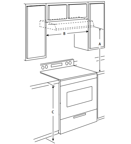
- A.24 ” min. for electric cooking surfaces
27” min. for gas cooking surfaces
30” suggested max. - B. 30” min. cabinet opening width for 30” models and 36” min. cabinet width for 36” models
- C.. 36” base cabinet height
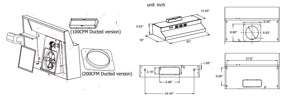
PRODUCT DIMENSIONS
RANGE HOOD USE INSTRUCTIONS
USE INSTRUCTIONS
The range hood is designed to remove smoke and cooking vapors from the cooktop area. For best results, start the hood before cooking and allow it to operate several minutes after the cooking is complete to clear all smoke from the kitchen.
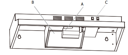
- A. LED lights
- B. Grease filter
- C. Control knobs
IMPORTANT
Exterior Surfaces Do not use soap-filled scouring pads, abrasive cleaners, Cooktop Polishing Creme, steel wool, gritty washcloths, or paper towels. To avoid damage to the stainless steel, do not use cleaners that contain chlorine.
Cleaning Method:
Clean the stainless with warm soapy water using a clean sponge or cloth. Rinse with clean water and dry with a soft clean cloth. DO NOT USE any cleaners like Stainless Steel cleaners or any other types of cleaners containing any abrasive, chlorides, chlorines, or ammonia. It is recommended to use mild dish soap and water or a 50/50 solution of water and vinegar.
To clean or replace the grease filter:
- Take down lamp-chimney, take down screw.

- According to “
 ” direction loosen Plastic seat

- To clean the grease filter, soak the filters in hot water using a mild detergent. Rinse well and shake to dry.

NOTE
The grease filter is dishwasher-safe. To avoid grease filter damage while cleaning, place the filter into the dishwasher top rack for cleaning According to ” the ” direction loosens the Plastic seat.
WARNING
Electrical Shock Hazard Disconnect power before servicing. Replace all parts and panels before operating. Failure to do so can result in death or electrical shock.
Assembly LED Lights (lamp not included)
- Use an E26 LED Bulb, Spin to tighten E26 light bulb (120v, Max 9W, LED only)
- Place the lampshade in the hole


VENTING REQUIREMENTS
- Do not terminate the vent system in an attic or other enclosed area.
- Do not use a 4” (102 mm) laundry-type wall cap.
- Use a metal vent only. A rigid metal vent is recommended. Plastic or metal foil vent is not recommended.
- The length of the vent system and the number of elbows should be kept to a minimum to provide efficient performance.
For the most efficient and quiet option:
- Use no more than three 90° elbows.
- Make sure there is a minimum of 24” (610mm) of straight vent between the elbows if more than 1 elbow is used.
- Do not install 2 elbows together.
- Use clamps or duct tape to seal all joints in the vent system.
- The vent system at the exit must have a cold air damper. Use caulking to seal the exterior wall or roof opening around the cap.
- Best performances are reached with straight piping, without elbows, and using a smooth pipe.
Cold Weather Installations
An additional back draft damper should be installed to minimize backward cold air flow and a thermal beak should be installed to minimize the conduction of outside temperatures as part of the vent system. The damper should be on the cold air side of the thermal break. The break should be as close as possible to where the vent system enters the heated portion of the house.
Makeup Air
Local building codes may require the use of makeup air systems when using ventilation systems greater than the specified CFM of air movement. The specified CFM varies from locale to locale. Consult your HVAC professional for specific requirements in your area.
Venting Methods
The vent system can terminate either through the roof or the wall. Use 3.25” x 10” (83 x 254 mm) rectangular with a maximum vent length of 35 ft (10.7 m) for the vent system.
NOTE
Flexible vent is not recommended. A flexible vent creates both back pressure and air turbulence that greatly reduces performance.

Calculating Vent System Length
To calculate the length of the system you need, add the equivalent feet (meters) for each vent piece used in the system. Roof Venting Wall Venting VENTING REQUIREMENTS These directions are for rectangular vent installation only. If you choose to use round rigid metal venting the minimum diameter to use is “‘8”.?
3 mm x 254 mm) rectangular Vent System

Example Vent System

PREPARE THE LOCATION
- Disconnect power.
- Select a flat surface for assembling the range hood. Place covering over that surface.
- Lift the range hood and set it upside down onto a covered surface.
- If the cabinet has a recessed bottom, add “two – 2” wide filler strips. Length and thickness are determined by recess dimensions. Four flat-head wood screws or machine screws with washers and nuts to attach filler strips in the locations shown.

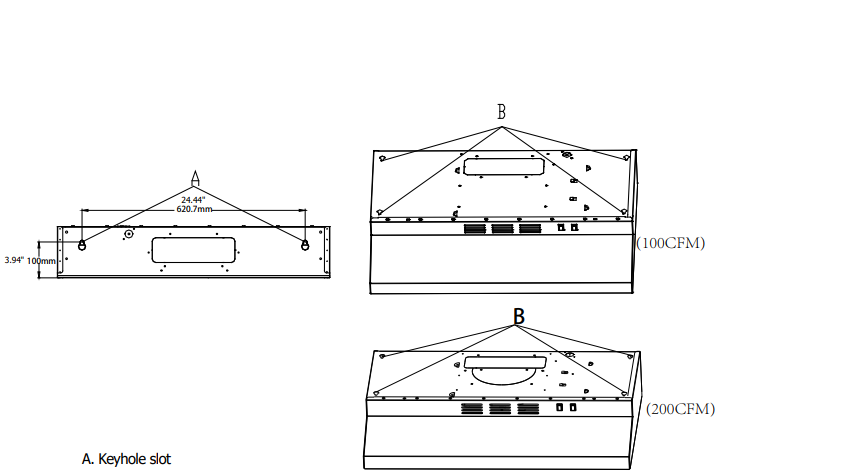
- Lift the range hood up under the cabinet and determine the final location y centering it beneath the cabinet. Mark on the underside of the cabinet the location of the 4 keyhole mounting slots on the range hood (See slot dimensions on page 6). Mark rear mounting screw hole locations. Set the range hood aside on a covered surface.

- Use a 0.08” drill bit and drill 4 pilot holes as shown for top range hood support.
NOTE: Make the drill holes on the thin area of the slot.

- Install the 4 – 5 mm x 19 mm mounting screws in the pilot holes. Leave about 0.25” (6.4 mm) space between screw heads and cabinet to slide the range hood into place.

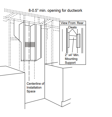
- Install framing for hood rear support If drywall is present, using the rear mounting screw hole locations marked in the previous step cut away enough drywall to expose 2 vertical studs at the rear mounting screw holes locations. Install horizontal support at least 2” X 4” between two wall studs at the rear mounting screw holes location. The horizontal support must be flush with the room side of the studs. Use cleats behind both sides of the support to secure to wall studs. Reinstall drywall and refinish. IMPORTANT – Framing must be capable of supporting 100 lbs.


Roof Venting
cutout on the underside of cabinet top and bottom:
- Mark lines from the back wall on the centerline of the underside of the cabinet.
- Mark lines to the right and left of the centerline on the underside of the cabinet.
- Use a saber or keyhole saw to cut a rectangular opening for the vent. Repeat steps 1-3 for the underside of the top of the cabinet.
- The actual size of the product is below, and the user is installed according to the actual demand.


Wall Venting
To make a 4 ” x 10.5” (108 mm x 267 mm) rectangle in the wall:
- Mark lines from the back wall on the centerline of the underside of the cabinet.
- Mark lines to the right and left of the centerline on the underside of the cabinet.
- Use a saber or keyhole saw to cut a rectangular opening for the vent.
- Use a saber or keyhole saw to cut a rectangular opening for the vent.
- The actual size of the product is below, and the user is installed according to the actual demand


Roof Venting
(7″ Circular interface) To make a 7.5″(190mm) rectangular cutout on the underside of the cabinet top and bottom:
- Mark lines from the back wall on the centerline of the underside of the cabinet.
- Mark lines to the right and left of the centerline on the underside of the cabinet.
- Use a saber or keyhole saw to cut a rectangular opening for the vent.
- Repeat steps 1-3 for the underside of the top of the cabinet.
- The actual size of the product is below, and the user is installed according to the actual demand

INSTALLING THE HOOD
Power Supply Cable Installation
- For direct wire installations, run the home power supply cable according to the National Electric Code or CSA standards and local codes and ordinances.
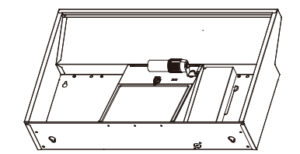
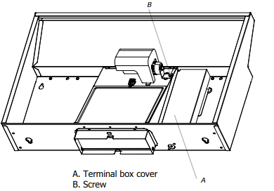
NOTE Do not reconnect power until the installation is complete. Before starting the installation, remove the vent grill and grease filters. - Remove the screws from the terminal box cover. Remove the terminal box cover and set it aside.

- Remove the screws from the terminal box cover. Remove the terminal box cover and set it aside. remove the power supply knockout from the top or rear of the vent hood (depending on the incoming location of your home power supply cable) and install a UL-listed or CSA-approved 0.5” strain relief.

- Lift the hood into the final position Feed enough electrical wire through the 0.5” UL listed or CSA-approved strain relief to make connections in the terminal box. Tighten the strain relief screws.
- Position the range hood so that the large end of the keyhole slots is over the mounting screws. Then push the hood toward the wall so that the screws are in the neck of the slots. Tighten the mounting screws, making sure the screws are in the narrow neck of slots.
- Add the 2 rear 0.19″ * 1.94″ (0.49 * 5.0 cm) rear mounting screws into the narrow neck of the rear keyhole slots.
- Seal joints with vent clamps or duct tape to make them secure and airtight.
- Check that the back draft dampers work properly.

1-YEAR LIMITED WARRANTY
This is the only express warranty for this product and is in lieu of any other warranty or condition. This product is warranted to be free from defects in material and workmanship for a period of one (1) year from the date of original purchase. During this period, your exclusive remedy is repair or replacement of this product or any component found to be defective, at our option; however, you are responsible for all costs associated with returning the product to us and our returning the product or component under this warranty to you. If the product or component is no longer available, we will replace it with a similar one of equal or greater value.
This warranty does not cover wear from normal use or operation that does not comply with the instruction manual or damages to the product resulting from accident, alteration, abuse, or misuse. This warranty extends only to the original consumer purchaser or gift recipient. Keep the original sales receipt, as proof of purchase is required to make a warranty claim. We exclude all claims for special, incidental, and consequential damages by breach of express or implied warranty. All liability is limited to the amount of the purchase price.


